Lens Machining Machine
- Summary
- Abstract
- Description
- Claims
- Application Information
AI Technical Summary
Benefits of technology
Problems solved by technology
Method used
Image
Examples
Embodiment Construction
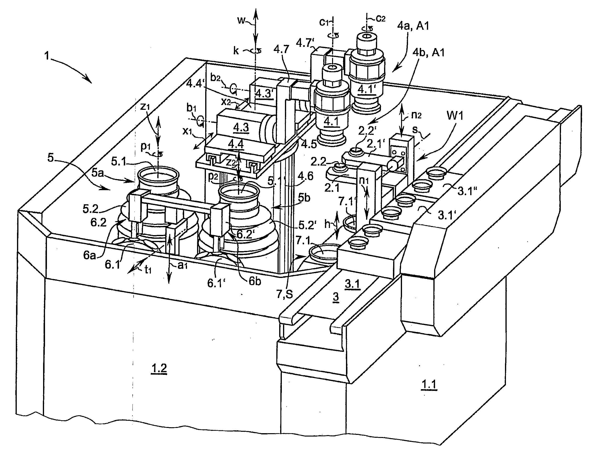
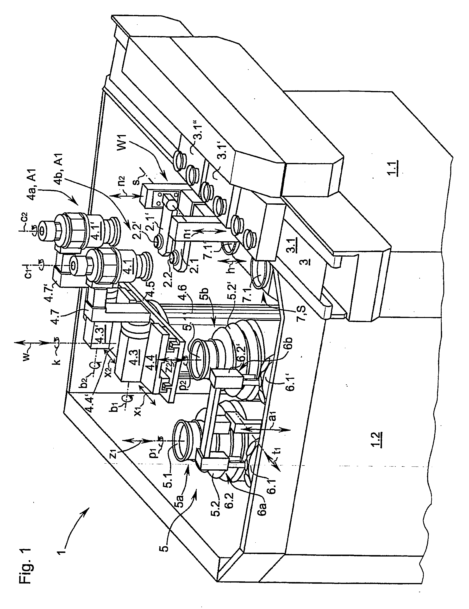
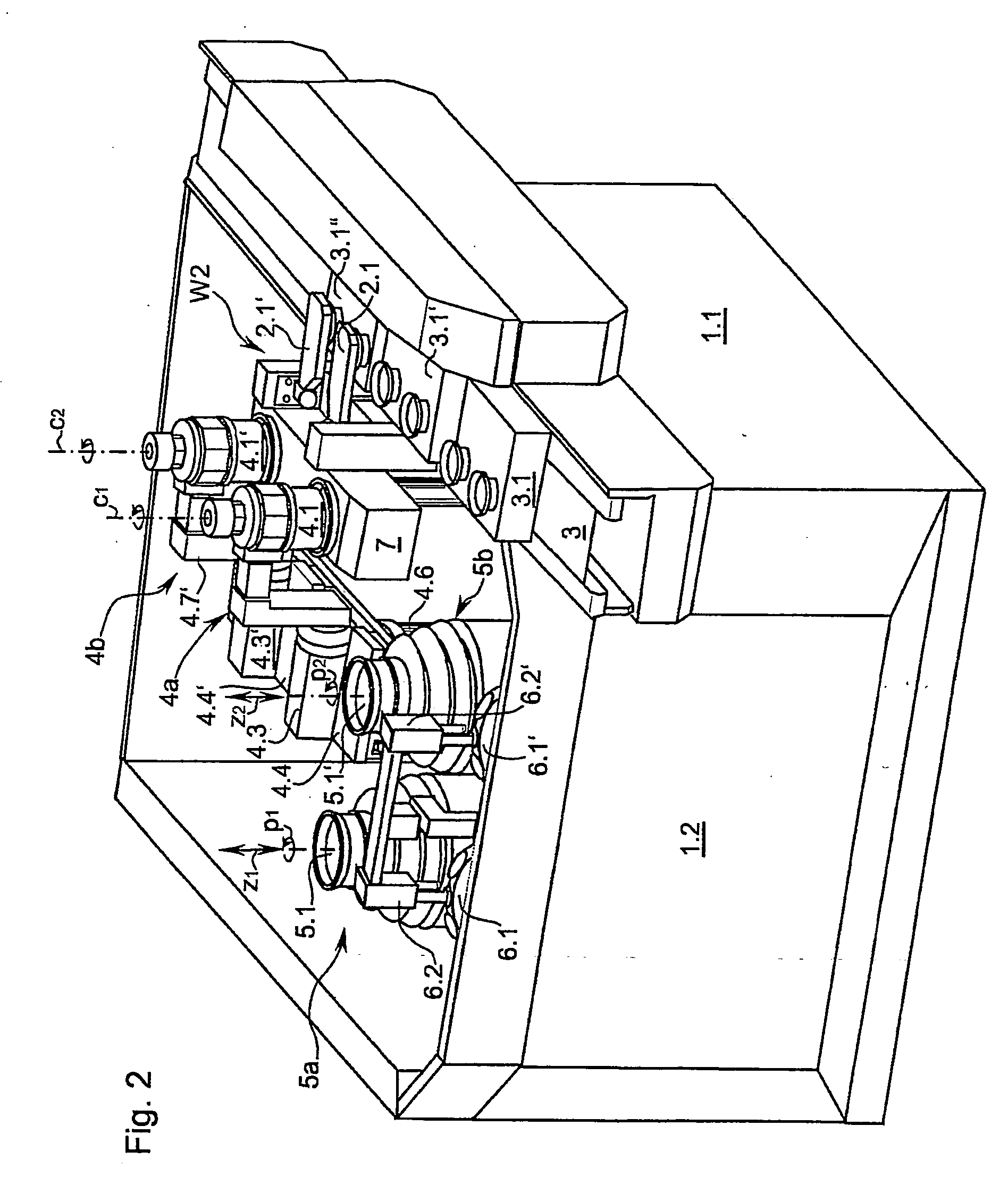
[0028]A machining machine as represented in FIG. 1 and configured as a polishing machine 1 has a conveyor belt 3 for optical lenses or workpiece boxes 3.1-3.1″, by which the transport boxes 3.1-3.1″ are delivered to a pair of workpiece changers 2.1, 2.1′ of the polishing machine 1. The respective workpiece changer 2.1, 2.1′ is configured as a swivel arm, which can swivel 180° about a swivel axis s. At the free end of the respective swivel arm 2.1, 2.1′ there is provided a suction cup 2.2, 2.2′ to receive a workpiece, or lens. The suction cup 2.2, 2.2′ is connected via pneumatic lines (not shown) to a low pressure receiver or pump (not shown). In order to pick up the lenses or pass the lenses on, the workpiece changer 2.1, 2.1′ furthermore has a linear guide able to travel in the direction of a respective lowering axis n1, n2, not further represented, by which the two swivel arms 2.1, 2.1′ can move essentially in the vertical direction, perpendicular to the swivel axis s. To pick up ...
PUM
| Property | Measurement | Unit |
|---|---|---|
| Time | aaaaa | aaaaa |
| Angle | aaaaa | aaaaa |
| Displacement | aaaaa | aaaaa |
Abstract
Description
Claims
Application Information
 - R&D
- Intellectual Property
- Life Sciences
- Materials
- Tech Scout
- Unparalleled Data Quality
- Higher Quality Content
- 60% Fewer Hallucinations
Browse by: Latest US Patents, China's latest patents, Technical Efficacy Thesaurus, Application Domain, Technology Topic, Popular Technical Reports.
© 2025 PatSnap. All rights reserved.Legal|Privacy policy|Modern Slavery Act Transparency Statement|Sitemap|About US| Contact US: help@patsnap.com


