
Canopy structure and a wind turbine

a technology of canopy structure and wind turbine, which is applied in the manufacture of final products, machines/engines, mechanical equipment, etc., can solve the problems of difficult transportation, large storage facilities, and high manufacturing time, and achieve the effect of improving the canopy structur

Active Publication Date: 2019-09-05
SIEMENS GAMESA RENEWABLE ENERGY AS
View PDF12 Cites 3 Cited by
  • Summary
  • Abstract
  • Description
  • Claims
  • Application Information

AI Technical Summary

Benefits of technology

The patent describes a canopy structure for wind turbines that is made up of standard panels. These panels are designed in a way that they can be easily transported, assembled, and used for different wind turbine models. The panels can be curved, which increases the space inside the canopy structure. They are also lightweight and can be lengthened and widthened for larger wind turbines. This design reduces the need for multiple parts and tools, resulting in cost savings. Overall, the standard panels make it easier to construct and maintain wind turbine canopies.

Problems solved by technology

However, due to the increasing size of the nacelles, either numerous cover sheets need to be prepared which are then placed individually on the outside of the nacelle support structure.
This however is very time consuming from a manufacture point of view.
Alternatively, bigger cover sheets can be made which however requires large storage facilities before assembly and may not be easy to transport.
Either way, the panels are often custom-made for each individual placement in the overall canopy structure layout, which requires individual and labor-intensive preparation procedures, e.g. different molds or cutting tools have to be used before a complete canopy structure is prepared.

Method used


Image

  • Canopy structure and a wind turbine
  • Canopy structure and a wind turbine
  • Canopy structure and a wind turbine

Examples


Embodiment Construction

[0042]In the Figures, like reference numerals designate like or functionally equivalent elements, unless otherwise indicated.

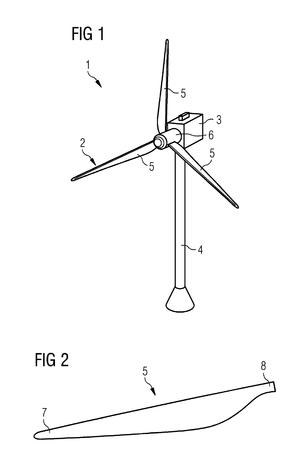
[0043]FIG. 1 shows a wind turbine 1 according to one embodiment.

[0044]The wind turbine 1 comprises a rotor 2 connected to a generator (not shown) arranged inside a nacelle 3. The nacelle 3 is arranged at the upper end of a tower 4 of the wind turbine 1.

[0045]The rotor 2 comprises three rotor blades 5. The rotor blades 5 are connected to a hub 6 of the wind turbine 1. Rotors 2 of this kind may have diameters ranging from, for example, 30 to 160 meters or even more. The rotor blades 5 are subjected to high wind loads. At the same time, the rotor blades 5 need to be lightweight. For these reasons, rotor blades 5 in modern wind turbines 1 are manufactured from fiber-reinforced composite materials. Therein, glass fibers are generally preferred over carbon fibers for cost reasons. Oftentimes, glass fibers in the form of unidirectional fiber mats are used.

[0046]FIG. ...


PUM


Abstract

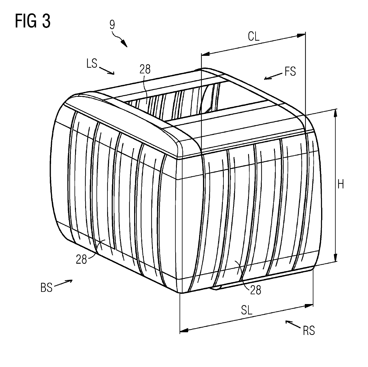
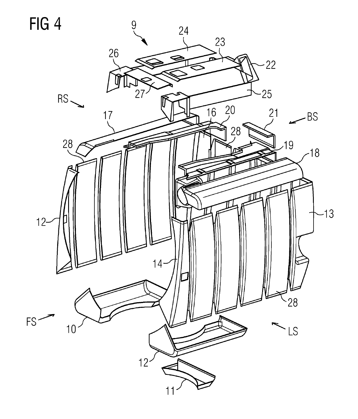
Provided is a canopy structure for a nacelle of a wind turbine, including at least one side and a plurality of standard panels which all have the same length and the same width, wherein the at least one side is at least partly formed from the plurality of standard panels, and wherein each standard panel includes a flange) which runs only along one edge of the standard panel. Advantageously, the canopy structure including the standard panels is able to reduce the need of a high number of different canopy parts. The amount of different types of molds or tools for producing the standard panels is reduced which leads to a more cost-effective production of the canopy structure.

Description

CROSS-REFERENCE TO RELATED APPLICATIONS[0001]This application claims priority to European application No. 18159737.8, having a filing date of Mar. 2, 2018, the entire contents of which are hereby incorporated by reference.FIELD OF TECHNOLOGY[0002]The following relates to a canopy structure for a nacelle of a wind turbine and to a wind turbine comprising such a canopy structure.BACKGROUND[0003]As wind turbines get bigger and bigger, the size of the nacelles likewise increases to accommodate the size increasing equipment like generator, gearbox, power electronics or the like. In particular, the weight follows along this trend. Nacelles are usually provided with an outside cover, named as canopy structure, surrounding an interior of the nacelle, wherein the canopy structure is normally prepared from custom-made cover sheets or panels which are attached to a nacelle support structure. As such, the cover sheets are usually not load-carrying but provide some structural stiffness to the na...

Claims


Application Information

Patent Timeline
Patent Type & Authority Applications(United States)
IPC IPC(8): F03D13/10F03D80/80
CPCF03D13/10F05B2240/14F05B2230/604F03D80/80F03D80/00Y02E10/72Y02P70/50
Inventor KRUSE, THOMAS
Owner SIEMENS GAMESA RENEWABLE ENERGY AS
Learn More