
Intelligent cooling method combining passive and active cooling components

a passive and active cooling technology, applied in the direction of lighting and heating apparatus, process and machine control, instruments, etc., can solve the problems of passive cooling method inadequate, active cooling method consuming external power for its operation, and heat generation when these devices are operated

Active Publication Date: 2008-02-14
ORACLE INT CORP
View PDF8 Cites 39 Cited by
  • Summary
  • Abstract
  • Description
  • Claims
  • Application Information

AI Technical Summary

Problems solved by technology

All semiconductor devices have some form of conduction resistance which leads to generation of heat when these devices are operated.
Although heat pipe passive cooling method is currently quite effective in cooling high power semiconductors, the increasing power dissipation of future semiconductors may render this passive cooling method inadequate due to physical limitations of size and rate of heat transfer.
However, active cooling methods consume external power for their operation.
Thus, in instances when the power supply to the active cooling components is interrupted or fails, the semiconductor may reach undesirable temperatures.

Method used


Image

  • Intelligent cooling method combining passive and active cooling components
  • Intelligent cooling method combining passive and active cooling components
  • Intelligent cooling method combining passive and active cooling components

Examples


Embodiment Construction

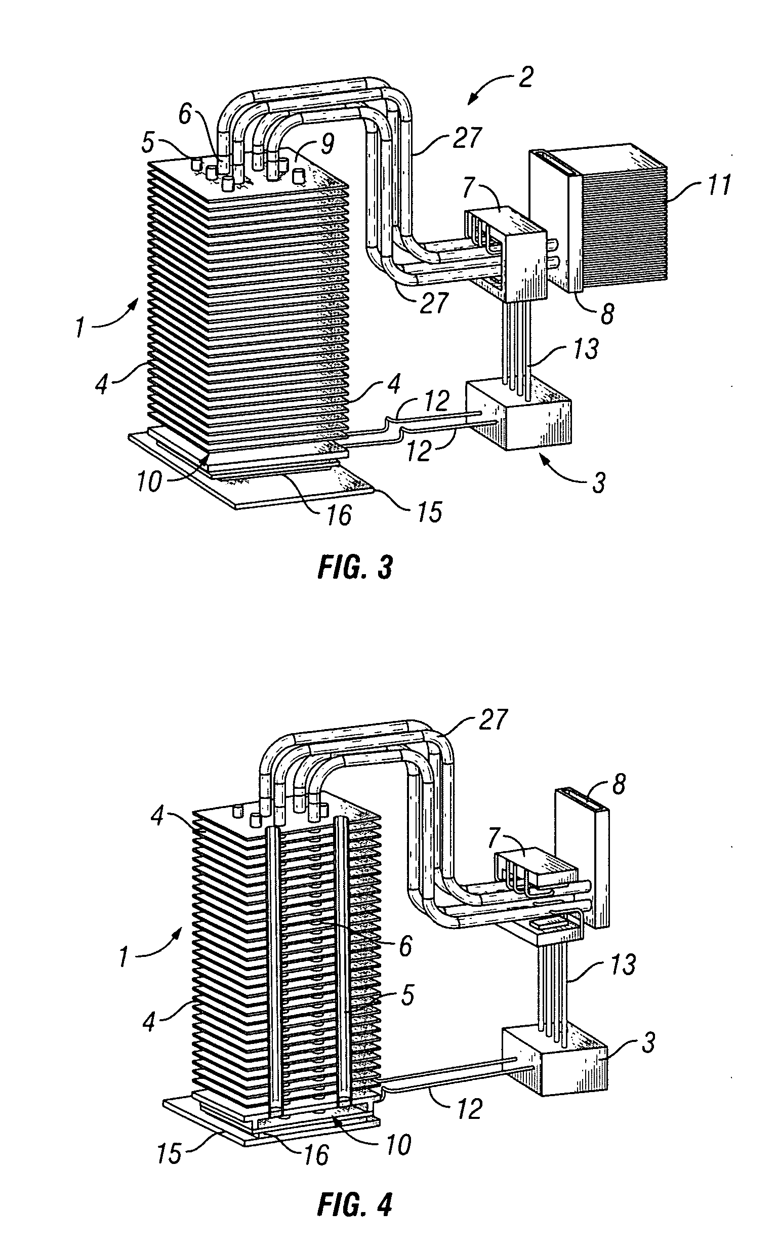
[0023]In one aspect, some embodiments disclosed herein relate to methods and systems for effectively transferring heat away from a desired location. In particular, embodiments of the present invention relate to methods and systems utilizing a passive cooling means to transfer heat, an active cooling means to transfer heat and a means to control the rate of active cooling. The passive cooling means may involve using heat pipes. The active cooling means may involve using magneto-hydro-dynamic (MHD) fluid. The invention further involves controlling the rate of active cooling means through a controller, for e.g., a multiple-input-multiple-output (MIMO) controller.

[0024]Embodiments of the present invention are described in detail below with respect to the drawings. Like reference numbers are used to denote like parts throughout the figures.

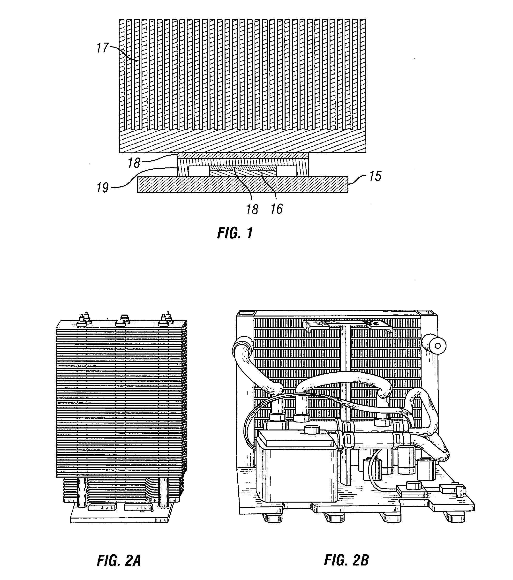
[0025]FIG. 3 illustrates a cooling system in accordance with the embodiments of the present invention. The passive cooling component 1 is combined wit...


PUM


Abstract

A method for cooling a semiconductor including passive cooling including transferring heat via passive cooling components; active cooling including transferring heat via active cooling components; and controlling the active cooling based on temperature of the semiconductor. A cooling system for a semiconductor including: a passive component in thermal contact with the semiconductor; an active cooling component in thermal contact with the semiconductor; and a controller controlling the active cooling component.

Description

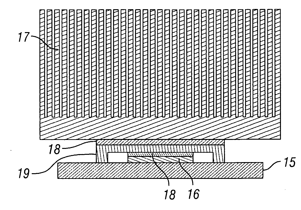
BACKGROUND OF INVENTION[0001]All semiconductor devices have some form of conduction resistance which leads to generation of heat when these devices are operated. The flow of heat starts at the semiconductor junction through which electric current travels. This heat is conducted from the device body onto the package that the semiconductor is housed in, and then to the air. This heat energy increases the temperature of the semiconductor. If the heat is not dissipated from the semiconductor fast enough, the semiconductor temperature may increase beyond the specified operating temperature. A heat sink is an environment or object that absorbs heat from another object using thermal contact. Heat sinks are used to aid in the absorption of heat from the surface of a semiconductor.[0002]FIG. 1 shows an example of a heat sink. The heat producing semiconductor 16 is attached to a substrate 15. A metal lid 19 is placed in close proximity to the semiconductor 16. The metal lid 19 and the semicon...

Claims


Application Information

Patent Timeline
IPC IPC(8): H01L23/34
CPCH01L23/34H01L23/473H01L2924/0002H01L2924/00
Inventor OUYANG, CHIEN
Owner ORACLE INT CORP
Learn More