Eureka AIR delivers breakthrough ideas for toughest innovation challenges, trusted by R&D personnel around the world.

Diamond-like carbon thermoelectric conversion devices and methods for the use and manufacture thereof

a technology of diamond-like carbon and thermoelectric conversion device, which is applied in the manufacture of electrode systems, electric discharge tube/lamps, and thermoelectric devices. it can solve the problems of inconvenient use, limited potential use of field emission devices, and inability to meet the requirements of use, etc., and achieves high reliability, reduced costs, and convenient formation

Inactive Publication Date: 2008-02-07
SUNG CHIEN MIN
View PDF59 Cites 21 Cited by
  • Summary
  • Abstract
  • Description
  • Claims
  • Application Information

AI Technical Summary

Benefits of technology

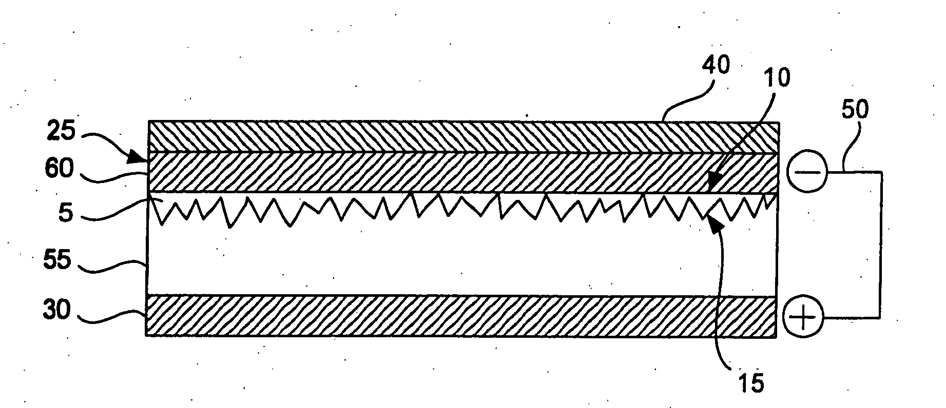
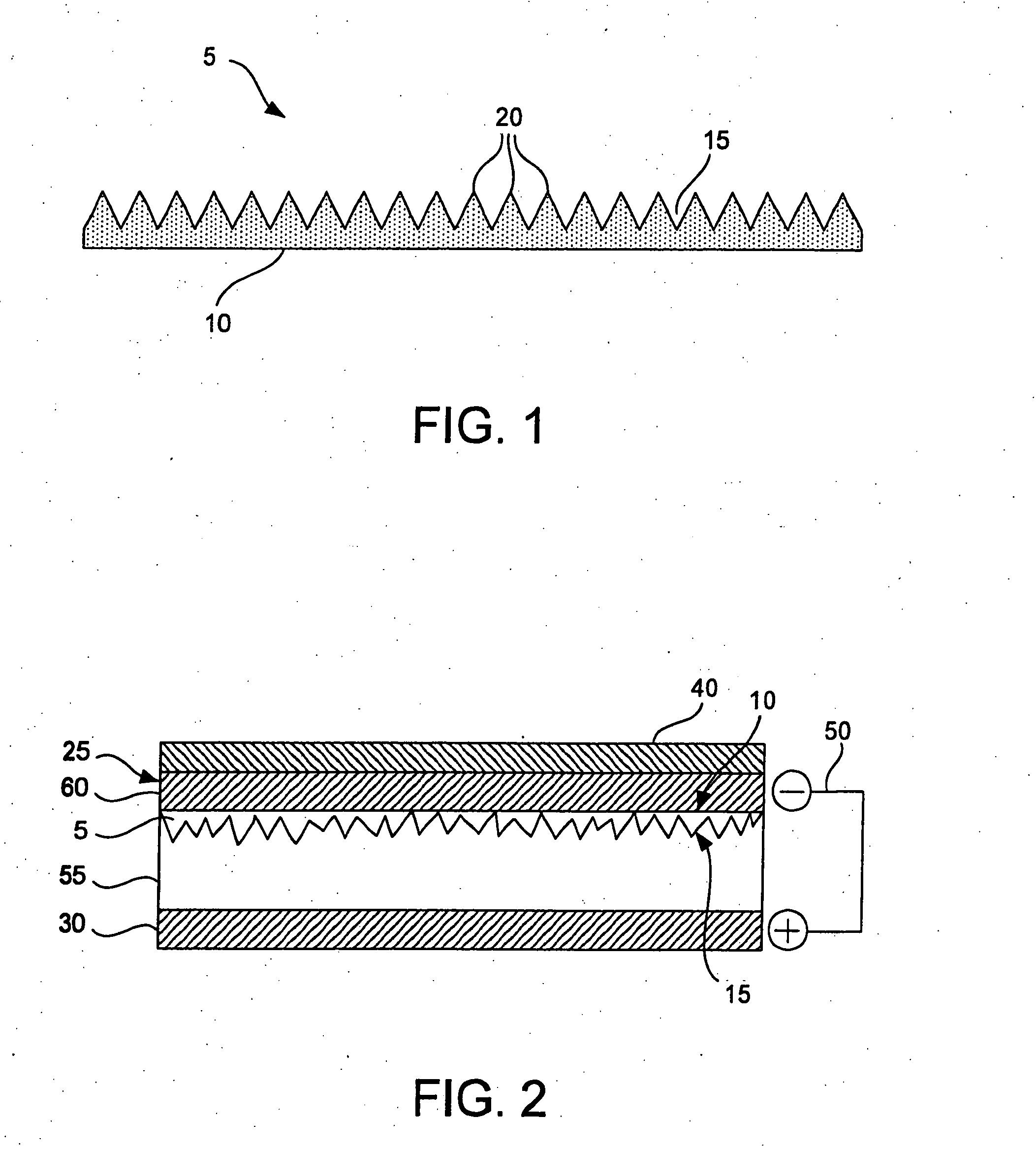
[0008] Accordingly, the present invention provides materials, devices, and methods for conversion of energy using a thermoelectric conversion device. In one aspect, the present invention provides a diamond-like carbon thermoelectric conversion device having improved conversion efficiencies and increased reliability. The device can include a first electrode having a base member with a layer of diamond-like carbon material coated over at least a portion thereof. A dielectric intermediate member can be electrically coupled to the diamond-like carbon material. The dielectric intermediate member can include a conductive material dispersed therein. A second electrode can also be electrically coupled to the intermediate member opposite the diamond-like carbon material.
[0012] The diamond-like carbon material can be amorphous carbon. In yet another embodiment, the first electrode and the second electrodes can be flexible. Combined with a flexible intermediate member, the entire thermoelectric conversion device can be flexible, thus providing for great versatility in application and use.
[0014] The thermoelectric conversion devices of the present invention can be configured as either, or both, an electrical generator and cooling device. In one aspect, an energy collector can be coupled to the first electrode, opposite the diamond-like carbon material such that the diamond-like carbon thermoelectric conversion device is configured as an electrical generator. This embodiment can operate under conversion of thermal and / or photonic energy into electrical energy. Alternatively, or in addition to an electrical generator, a voltage source can be operatively connected between the first and second electrodes such that the diamond-like carbon thermoelectric conversion device is configured as a cooling device. In this way, the device can selectively control heat flow across the device to cool an adjacent structure or space.
[0016] The thermoelectric conversion devices of the present invention can be conveniently formed using various techniques such as vapor deposition. The intermediate member can be formed by any method known in the art, particularly using a preformed solid, screen printing, and thin film deposition. In addition, the devices of the present invention do not require formation of a vacuum space and are typically completely solid throughout. As a result, the devices of the present invention are capable of mass production at reduced costs and are highly robust and reliable for an extended period of time.
[0017] In an alternative aspect, the devices of the present invention can be subjected to a heat treatment to consolidate interfacial boundaries and reduce material defects.

Problems solved by technology

Although basically successful in many applications, thermionic devices have been less successful than field emission devices, as field emission devices generally achieve a higher current output.
Despite this key advantage, most field emission devices suffer from a variety of other shortcomings that limit their potential uses, including materials limitations, versatility limitations, cost effectiveness, lifespan limitations, and efficiency limitations, among others.
While such attempts have achieved moderate success, a number of limitations on performance, efficiency, and cost, still exist.
Therefore, the possible applications for field emitters remain limited to small scale, low current output applications.

Method used


Image

  • Diamond-like carbon thermoelectric conversion devices and methods for the use and manufacture thereof
  • Diamond-like carbon thermoelectric conversion devices and methods for the use and manufacture thereof
  • Diamond-like carbon thermoelectric conversion devices and methods for the use and manufacture thereof

Examples


example 1

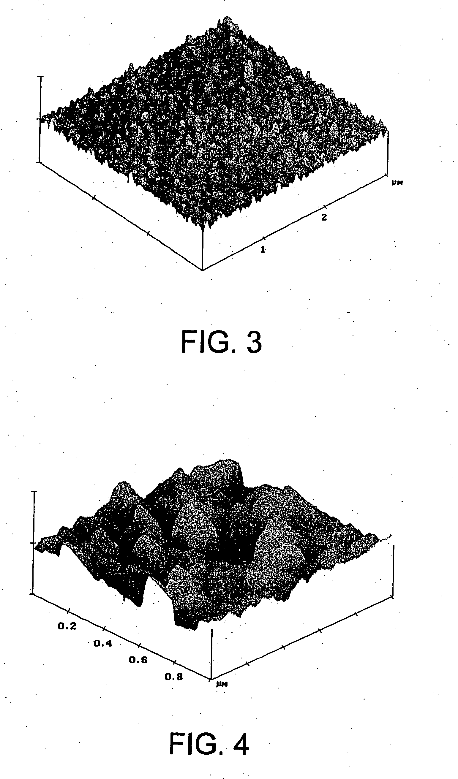
[0106] A copper foil is glued to a polyimide support layer. A one micron layer of amorphous diamond is deposited on the exposed copper foil electrode using a cathodic arc process. The amorphous diamond has a 50 nm asperity. An intermediate layer of PZT is deposited by screen printing to a thickness of 30 μm on the amorphous diamond. A layer of silver grease is coated on the PZT intermediate member by screen printing to form an anode. The assembly is then cured in an oven to drive off the binder used in screen printing and to consolidate the device. Attachment of wires to the copper electrodes can allow this thermoelectric conversion device to act as either an electrical generator by absorption of heat or as a cooling device by application of an electrical current.

example 2

[0107] The same procedure is followed as in Example 1, except the PZT layer is replaced by a mixture of graphite powder and hexagonal boron nitride powder.

example 3

[0108] The same procedure is followed as in Example 1, except the PZT layer is replaced by polyurethane with 7% carbon nanotubes dispersed therein in a pre-formed solid layer.


PUM


Abstract

Diamond-like carbon based thermoelectric conversion devices and methods of making and using the same, which have improved conversion efficiencies and increased reliability. The device can include a cathode having a base member with a layer of diamond-like carbon material such as amorphous diamond coated over the cathode. A dielectric intermediate member can be electrically coupled between the diamond-like carbon material and an anode. Various additional layers and configurations can allow for improved performance such as multiple cathode layers and / or multiple intermediate layers. The thermoelectric conversion devices can be configured as an electrical generator and / or a cooling device and can be conveniently formed. In addition, the devices of the present invention do not require formation of a vacuum space and are typically completely solid throughout. As a result, the devices of the present invention are susceptible to mass production at reduced costs and have improved conversion efficiencies and reliability.

Description

PRIORITY DATA [0001] This application is a continuation-in-part of U.S. patent application Ser. No. 11 / 157,179, filed Jun. 20, 2005, which is a continuation-in-part of U.S. patent application Ser. No. 11 / 112,724, filed on Apr. 21, 2005, which is a continuation-in-part of U.S. patent application Ser. No. 11 / 045,016, filed on Jan. 26, 2005, which is a continuation-in-part of U.S. patent application Ser. No. 10 / 460,052, filed on Jun. 11, 2003, now issued as U.S. Pat. No. 6,949,873, which is a continuation-in-part of U.S. patent application Ser. No. 10 / 094,426, filed on Mar. 8, 2002, now issued as U.S. Pat. No. 6,806,629, each of which are incorporated herein by reference. This application is also a separate continuation-in-part of U.S. patent application Ser. No. 11 / 510,478, filed Aug. 23, 2006, which is a continuation-in-part of U.S. patent application Ser. No. 11 / 157,179, filed Jun. 20, 2005, which is a continuation-in-part of U.S. patent application Ser. No. 11 / 112,724, filed on Apr...

Claims


Application Information

Patent Timeline
IPC IPC(8): H01L35/00B05D5/12
CPCH01J1/3048H01J3/021H01J2201/30457H01J29/04H01J9/025
Inventor SUNG, CHIEN-MIN
Owner SUNG CHIEN MIN
Why Eureka
Eureka Blog
Learn More