Substrate Treatment Apparatus

a technology of substrate and treatment apparatus, which is applied in the direction of instrumentation, program control, total factory control, etc., can solve the problems of deteriorating the reproducibility of substrate performance, difficulty in taking the correlation with single film performance, etc., and achieve the effect of preventing the stagnation of substrate performan

Active Publication Date: 2008-01-24
KOKUSA ELECTRIC CO LTD
View PDF2 Cites 26 Cited by
  • Summary
  • Abstract
  • Description
  • Claims
  • Application Information

AI Technical Summary

Benefits of technology

[0027] With respect to the conventional substrate treatment apparatus, in the steps for continuously forming stacked films on the substrate using a plurality of treatment chambers 6 to 9, for example, when the treatment times of the respective treatment chambers 6 to 9 differ from each other, the fluctuation of the loading interval of the substrate to the treatment chambers 6 to 9 or the stagnancy of the substrate in the treatment chambers 6 to 9 occurs. Accordingly, there arises a drawback such as the deterioration of the reproducibility of the substrate performance attributed to the fluctuation of the loading interval of the substrate to the treatment chambers 6 to 9 and a drawback of an extra heat history attributed to the stagnancy of the substrate in the treatment chambers 6 to 9, and also the difficulty in taking the correlation with the single film performance. Accordingly, even when the treatment times differ from each other for respective treatment chambers 6 to 9, there has been a demand for the development of a substrate conveyance control method which fixes the loading interval of the substrate into the treatment chambers 6 to 9 and prevents the stagnancy of the substrate in the treatment chambers 6 to 9.

Problems solved by technology

Accordingly, there arises a drawback such as the deterioration of the reproducibility of the substrate performance attributed to the fluctuation of the loading interval of the substrate to the treatment chambers 6 to 9 and a drawback of an extra heat history attributed to the stagnancy of the substrate in the treatment chambers 6 to 9, and also the difficulty in taking the correlation with the single film performance.

Method used


Image

  • Substrate Treatment Apparatus
  • Substrate Treatment Apparatus
  • Substrate Treatment Apparatus

Examples


Embodiment Construction

[0069] Hereinafter, an embodiment according to the invention is explained in conjunction with drawings.

[0070] Here, this embodiment is explained by taking a substrate treatment apparatus which treats a semiconductor substrate and a manufacturing method of a semiconductor device as an example. However, for example, the constitution and the manner of operation similar to the constitution and the manner of operation of this embodiment are applicable to a substrate treatment apparatus which treats an LCD substrate or the like.

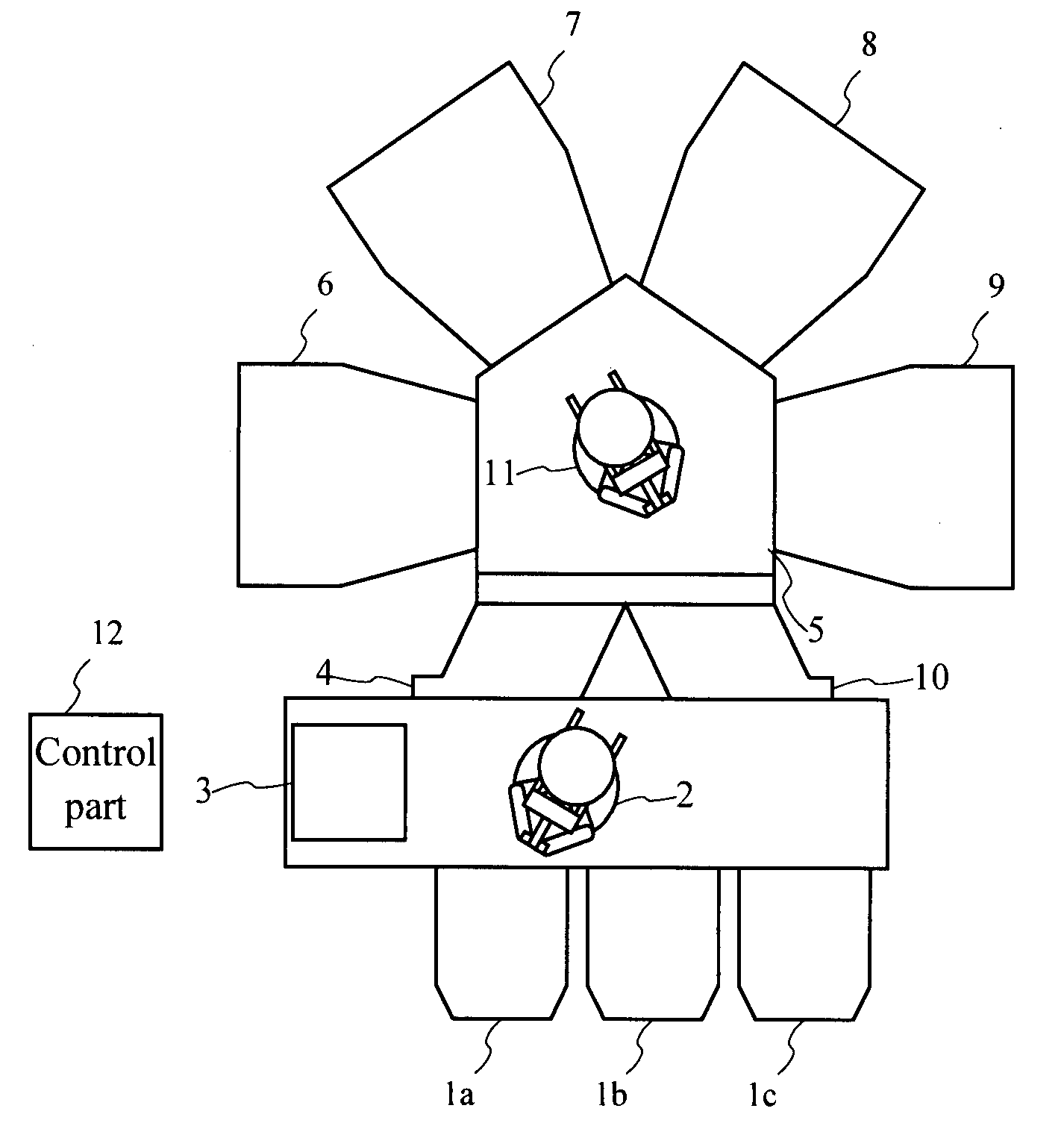
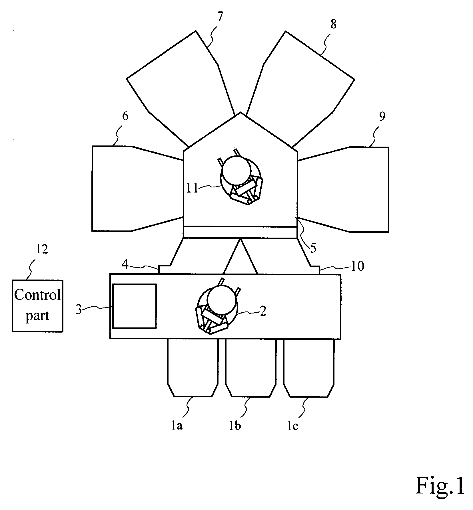
[0071] In FIG. 1, a constitutional example of a substrate treatment apparatus according to one embodiment of the invention is shown.

[0072] The substrate treatment apparatus of this embodiment is constituted of carrier stations (load ports: LP) 1a, 1b and 1c, an atmospheric-pressure atmosphere transfer machine (LH) 2, a substrate position correction unit (aligner: AU) 3, a first load-locking chamber (LM1) 4, a conveyance chamber 5 on which a vacuum atmosphere tra...


PUM

PropertyMeasurementUnit
pressureaaaaaaaaaa
timeaaaaaaaaaa
timeaaaaaaaaaa

Abstract

The present invention provides a substrate treatment apparatus which sets substrate loading intervals to treatment chambers to a fixed value and prevents the occurrence of stagnancy of substrates in the treatment chambers. The substrate treatment apparatus includes a substrate conveyance chamber 5 which has a substrate conveyance device 11, a plurality of treatment chambers 6 to 9 in which a treatment time of at least one treatment chamber differs from treatment times of other treatment chambers and the respective treatment chambers are communicated with the conveyance chamber, and a control part 12 which controls a conveyance operation of the substrate conveyance device by setting treatment schedules of the substrates. In sequentially treating a plurality of substrates by the treatment chambers based on the preset same treatment schedule, the control part, using a time corresponding to a sum of the treatment time of the treatment chamber having the longest treatment time out of the treatment chambers predetermined during the treatment schedule and conveyance times before and after the treatment time with respect to the treatment chamber as a reference substrate loading interval, sets the substrate loading interval of respective substrates to the firstly loaded treatment chamber.

Description

TECHNICAL FIELD [0001] The present invention relates to a substrate treatment apparatus which treats substrates, and more particularly to a substrate treatment apparatus which fixes loading intervals of the substrates to treatment chambers and prevents the generation of stagnancy of the substrates in the treatment chambers. BACKGROUND ART [0002] For example, a substrate treatment apparatus such as a semiconductor manufacturing apparatus which applies predetermined treatments to a semiconductor substrate (wafer) and an LCD manufacturing apparatus which applies predetermined treatments to an LCD (Liquid Crystal Display)-use glass substrate includes a plurality of treatment chambers therein, and the film forming treatment is applied to the substrate in each treatment chamber. Further, the substrate is transferred between the respective treatment chambers using a transfer machine. [0003] One example of general steps for treating the substrate using a substrate treatment apparatus which ...

Claims


Application Information

Patent Timeline
Patent Type & Authority Applications(United States)
IPC IPC(8): H01L21/677H01L21/02
CPCG05B2219/31002G05B2219/31274G05B2219/32277Y10T29/41H01L21/67276H01L21/67745G05B2219/45031Y02P90/02
Inventor TAKANO, SATOSHI
Owner KOKUSA ELECTRIC CO LTD
Why Eureka
Try Eureka