
Coated substrates and method of coating

a coating substrate and substrate technology, applied in electrographic processes, instruments, transportation and packaging, etc., can solve the problems of liquid film coatings that are not optically transparent, liquid film coatings that may not be consistent with quality standards, and liquid film coatings that experience a range of surface tension defects, etc., to achieve the effect of low surface tension, effective absence of haze, and surface tension of a portion

Inactive Publication Date: 2008-01-17
XEROX CORP
View PDF2 Cites 16 Cited by
  • Summary
  • Abstract
  • Description
  • Claims
  • Application Information

AI Technical Summary

Benefits of technology

[0005] One embodiment is a xerographic print comprising a substrate with a toner-based image printed thereon, the printed substrate including low surface tension portions having a surface tension of no more than about 22 mN/m at 25 Deg. C. resulting in a surface tension gradient field on the printed substrate, the printed substrate being coated with a coating comprising at least one surfactant and a film-forming polymer, the coating having a liquid phase surface tension at 25 Deg. C. not exceeding the surface tension of the low surface tension portions of the printed substrate by more than about 2 mN/m, the coating having substantially no pinholes and being sufficiently resistant to permeation by the fuser oil to exhibit an effective absence of haze 24 hours after application.
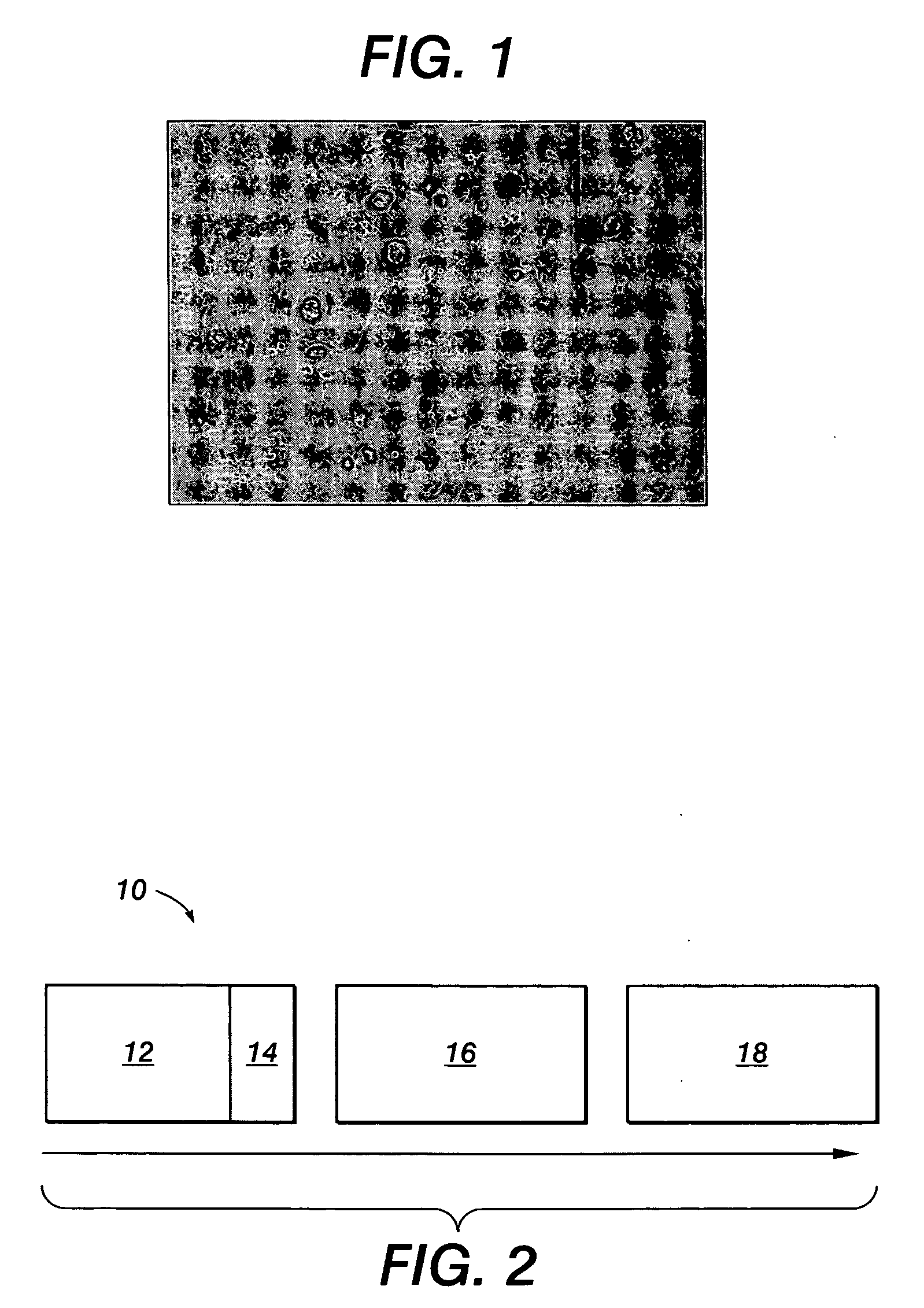
[0006] Another embodiment is a system for coating a printed image comprising an imager configured to print a xerographic image on a substrate, the imager including a fuser using fuser oil, and a coater configured to coat the printed image substantially immediately after printing with a coating having substantially no pinholes and an effective absence of haze 24 hours after application.
[0007] A further embodiment is a method comprising for

Problems solved by technology

The fusing conditions may not be consistent with quality standards for image permanence and durability in commerical printing markets.
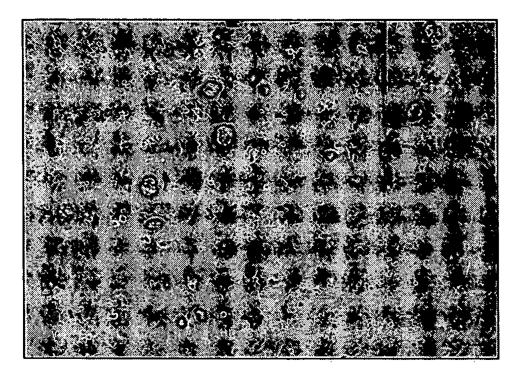
To the extent that the surface of the xerographic print at the time of coating contains residual low surface tension fuser release oil, liquid film coatings will experience a range of surface tension defects known to the industry.
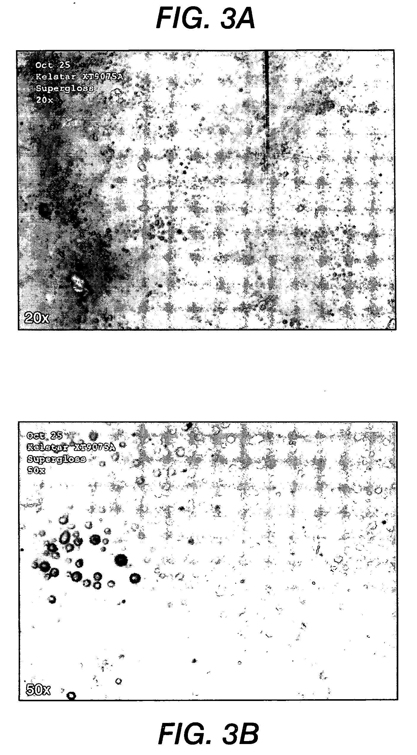
Another kind of defect, referred to as haze, occurs when a coating composition surrounds droplets of oil, resulting in a two phase mixture that is not optically transparent.
The delay required to overcome surface tension defects in this manner is typically 30 minutes to several hours after fusing.
It is required to have a time delay between the two operations because the requisite delay time cannot be accomodated in-line at process speeds of existing Xerographic engines.

Method used


Image

  • Coated substrates and method of coating
  • Coated substrates and method of coating
  • Coated substrates and method of coating

Examples


example 1

[0077] An apparatus was assembled including a Euclid offset gravure lab coater positioned to receive coated or uncoated paper (type of media) sheets hand-fed from the exit of a Xerox iGen3 fuser nip operating at approximately 500 mm / s process speed. The iGen3 fuser was connected to a paper delivery unit for non-imaged 75 gsm 4200 paper. In a typical experimental run, 50 sheets of 4200 paper were run through the fuser to stabilize the fuser oil metering system and then an unfused image on a selected substrate was tipped through fusing the test image. Immediately upon exit from the fusing nip, the image sheet was picked up by hand, taped to a leader sheet and passed through the coating nip of the Euclid coater receiving an application of test coating. The sheet was then manually fed to a UV Fusion curing station for drying and / or curing of the applied coating. A critical parameter was that the time from fuser nip exit to application of coating did not exceed 3 seconds.

[0078] The Eucl...

example 2

[0083] The procedure of Example 1 was repeated with the exception that 0.5 parts by weight (based upon 100 parts of the composition of formulation 1) defoamer BYK 088 (BYK-Chemie) was added. The results were comparable to those of Example 1.

example 3

[0091] The procedure of Example 1 was repeated with the exception that the 220 lpi gravure roll was replaced by a 160 lpi gravure roll to take into account the non-active (water) component of the coating and the aqueous latex based system shown below as Formulation 2 was used. The applied coating was dried using radiant heat supplied by the FusionUV lamps. The dry coating film was approximately 2 microns thick.

[0092] Formulation 2

Wt %Wt %WetDryAcrylic emulsionRohm & Haas Rhoplex HA1264.829.2Acrylic emulsionRohm & Haas Rhoplex I-207421.96.6Viscosity modifierRohm & Haas Acrysol ASE-603.61(thickener)Amino alcoholDow AMP-953.43.4Viscosity modifierElementis Rheolate 450SurfactantAir Products Surfynol 5040.60.6Surfactant3M Novec FC44320.10.1

[0093] In this example total surfactant is 1.9% of dry polymer. This composition succeeded in both wetting the print without pinholes and remaining free of time dependent haze.


PUM

PropertyMeasurementUnit
Temperatureaaaaaaaaaa
Timeaaaaaaaaaa
Timeaaaaaaaaaa

Abstract

Disclosed herein is a xerographic print comprising a substrate with a toner-based image printed thereon, the printed substrate including low surface tension portions having a surface tension of no more than about 22 mN / m at 25 Deg. C. resulting in a surface tension gradient field on the substrate, the printed substrate being coated with a coating comprising at least one surfactant and a film-forming polymer, the coating having a liquid phase surface tension at 25 Deg. C. not exceeding the surface tension of the low surface tension portions of the printed substrate by more than about 2 mN / m, the coating having substantially no pinholes and being sufficiently resistant to permeation by the fuser oil to exhibit an effective absence of haze 24 hours after application. A system and a method of applying a substantially pinhole-free and haze-free coating substantially immediately after print fusing also are disclosed.

Description

BACKGROUND [0001] The embodiments disclosed herein generally relate to coated substrates, efficient application of coating compositions, and systems and methods for analyzing the quality of coating compositions. [0002] Xerographic toners contain thermoplastic resins that are selected in part to ensure adhesion to media in a two roll fusing nip. Fusing takes place at a specified temperature, pressure and dwell time. The fusing conditions may not be consistent with quality standards for image permanence and durability in commerical printing markets. For this reason clear, protective overcoats may be applied over the print using some form of liquid film coating process followed by suitable drying and / or curing. To the extent that the surface of the xerographic print at the time of coating contains residual low surface tension fuser release oil, liquid film coatings will experience a range of surface tension defects known to the industry. One type of defect, referred to as “pin holes,” ...

Claims


Application Information

Patent Timeline
IPC IPC(8): G03G13/22B05C5/00G03C5/00
CPCG03G7/0006Y10T428/254G03G8/00G03G7/0046Y10T428/31786Y10T428/31855
Inventor SISLER, GORDONMCANENEY, T. BRIANTHOMPSON, DAVID MICHAELDIEHL, MICHAEL J.HALFYARD, KURT I.ANDERSON, CHRISTINE D.
Owner XEROX CORP
Learn More