Eureka AIR delivers breakthrough ideas for toughest innovation challenges, trusted by R&D personnel around the world.

Method for measuring work function

a work function and measurement method technology, applied in the direction of individual semiconductor device testing, discharge tube/lamp details, instruments, etc., can solve the problems of inconvenient thermionic emission, inability to accurately measure the work function, and metals with higher melting points that have a higher work function

Active Publication Date: 2008-01-17
TSINGHUA UNIV +1
View PDF5 Cites 8 Cited by
  • Summary
  • Abstract
  • Description
  • Claims
  • Application Information

AI Technical Summary

Benefits of technology

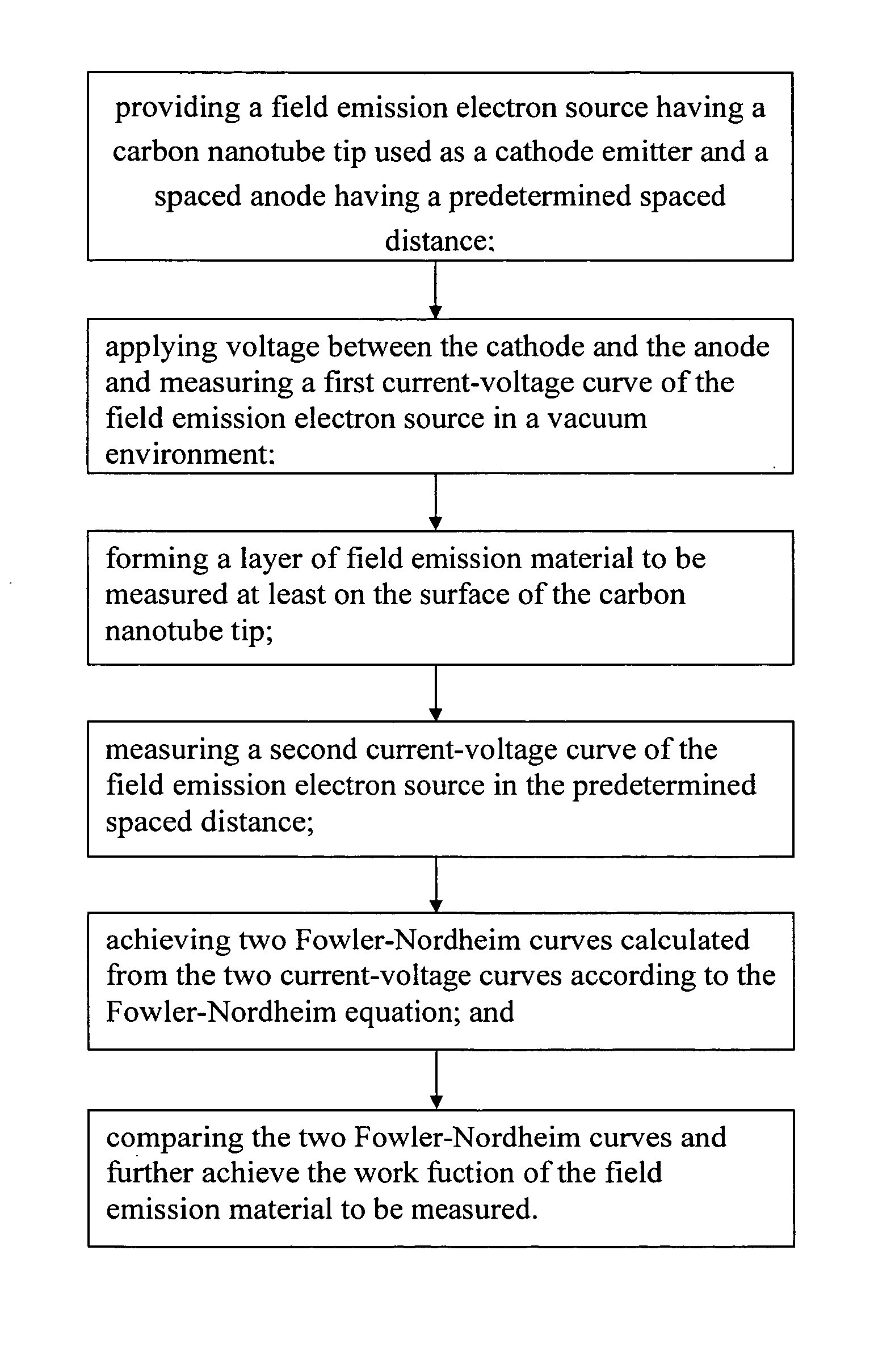
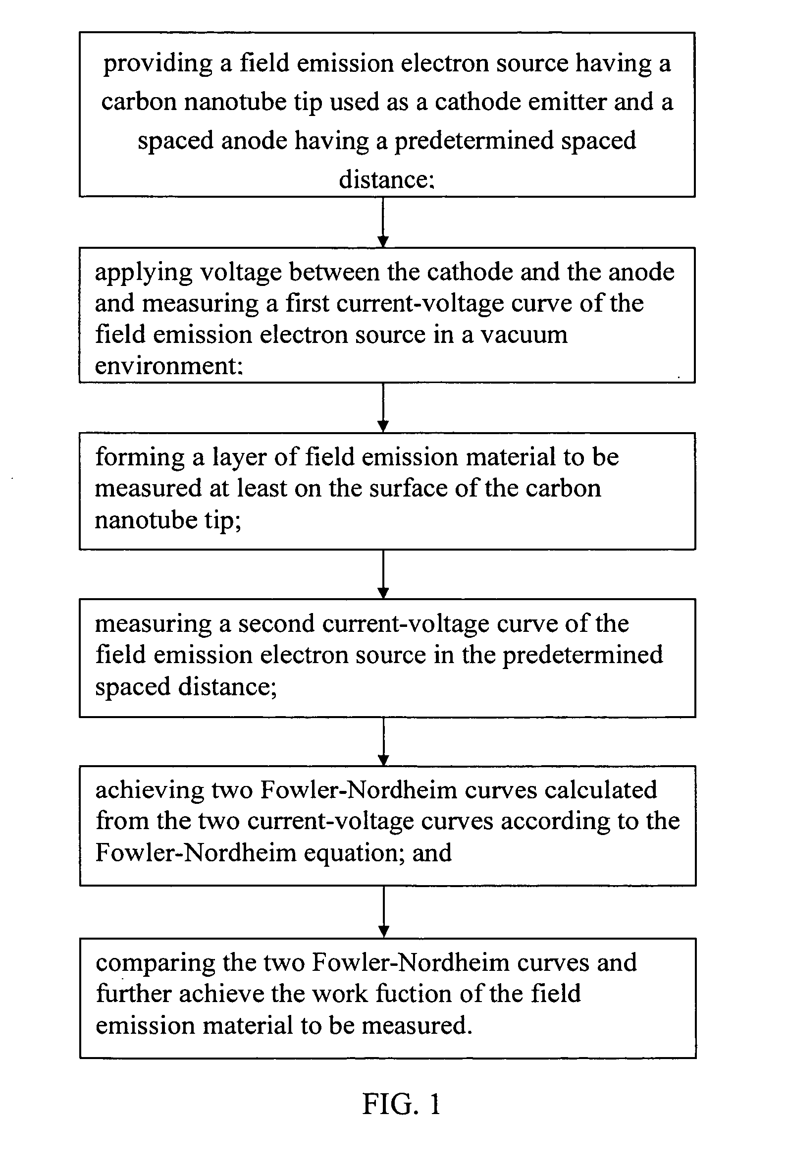
[0008] In the preferred embodiment, a method for measuring work function includes the steps of: (a) providing a field emission electron source having a carbon nanotube tip as a cathode emitter and a spaced anode, the nanotube tip and the spaced anode having a predetermined spaced distance therebetween; (b) applying a voltage between the cathode and the anode and measuring a first current-voltage curve of the field emission electron source in a vacuum environment; (c) forming a layer of a field emission material whose work function is to be measured, the layer of the field emission material being formed at least on the surface of the carbon nanotube tip; (d) measuring a second current-voltage curve of the field emission electron source in the same predetermined spaced distance; (e) achieving two Fowler-Nordheim curves calculated from the two current-voltage curves according to the Fowler-Nordheim equation; and (f) comparing the two Fowler-Nordheim curves and further calculating the work function of the field emission material to be measured.

Problems solved by technology

However, metals with higher melting points typically have a higher work function, which is bad (i.e., not conducive) to the thermionic emission.
Still furthermore, the work function cannot be accurately measured when different kinds of metal emitters are measured in the thermionic emission method.

Method used


Image

  • Method for measuring work function
  • Method for measuring work function
  • Method for measuring work function

Examples


Embodiment Construction

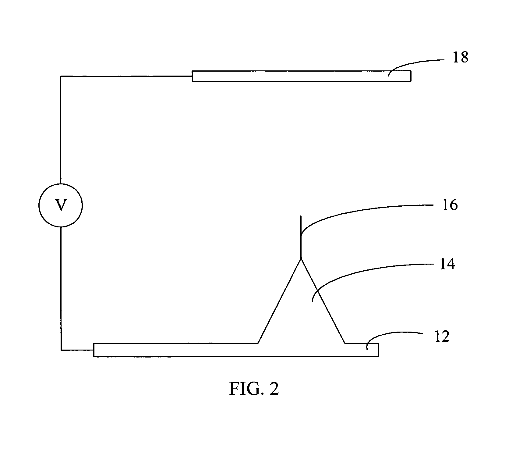
[0017] Reference will now be made to the drawings to describe embodiments of the present method for measuring work function, in detail.

[0018] Referring to FIG. 1, an embodiment of the present method for measuring work function is provided. The embodiment includes the following steps: [0019] step (a), providing a field emission electron source having an uncoated carbon nanotube tip, used as a cathode emitter, and a spaced anode plate, the nanotube tip and the spaced anode having a predetermined spaced distance; [0020] step (b), applying a voltage between the cathode and the anode and measuring a first current-voltage curve of the uncoated field emission electron source in a vacuum environment and at the predetermined spaced distance; [0021] step (c), forming a layer of a field emission material at least on a surface of the carbon nanotube tip to form a coated field emission electron source, with the work function of the field emission material to be measured; [0022] step (d), measur...


PUM


Abstract

A method for measuring work function includes the steps of: (a) providing a field emission electron source having a carbon nanotube tip as a cathode electrode and a spaced anode electrode, having a predetermined spaced distance therebetween; (b) applying a voltage between the cathode electrode and the anode electrode and measuring a first current-voltage curve of the field emission electron source in a vacuum environment; (c) forming a layer of field emission material at least on the surface of the carbon nanotube tip; (d) measuring a second current-voltage curve of the now-treated field emission electron source in the same conditions as that in the step (b); (e) achieving two Fowler-Nordheim curves calculated from the two current-voltage curves according to the Fowler-Nordheim equation; and (f) comparing the two Fowler-Nordheim curves and calculating the work function of the field emission material therefrom.

Description

BACKGROUND [0001] 1. Field of the Invention [0002] The invention relates generally to methods for measuring work function and, more particularly, to methods for measuring work function of field emission material. [0003] 2. Discussion of Related Art [0004] Work function is the minimum energy needed to remove an electron from a metal to a critical point immediately outside the metallic surface. The work function is an important property of the metal and is usually measured in electron volts. Generally, the measurement for work function of the metal is important for the research of electronic emission properties of the metal. Commonly, the electronic emission of the metal includes thermionic emission and field emission. In the thermionic emission, the electron gains its energy from the heat when the metal is heated to a relatively high temperature. In the field emission, the electron gains its energy from the electric field and is removed from the metallic surface because of an electro...

Claims


Application Information

Patent Timeline
Patent Type & Authority Applications(United States)
IPC IPC(8): G01R31/26
CPCG01N27/005
Inventor WEI, WEIJIANG, KAI-LIFAN, SHOU-SHAN
Owner TSINGHUA UNIV
Why Eureka
Eureka Blog
Learn More