Method of controlling an uninterruptible power supply apparatus

a power supply and uninterruptible technology, applied in the direction of electric vehicles, emergency power supply arrangements, transportation and packaging, etc., can solve the problems of small loss of switches, poor efficiency, large loss of switches, etc., to reduce reactive current, reduce high frequency ripple current, and high efficiency

Inactive Publication Date: 2008-01-17
DELTA ELECTRONICS INC
View PDF8 Cites 28 Cited by
  • Summary
  • Abstract
  • Description
  • Claims
  • Application Information

AI Technical Summary

Benefits of technology

[0013] It is an object of the present invention to provide a method of controlling an uninterruptible power supply apparatus for use in a single-phase AC / AC converter of the uninterruptible power supply apparatus having three arms. In prior arts, there were mentioned two kinds of conventional controlling modes, the first was (1) a DC voltage controlling mode for a voltage waveform on a bus line, and the second was (2) a full-wave rectifying waveform controlling mode for a voltage waveform on the bus line. The controlling method of the present invention tries to sustain the advantages of the two conventional controlling modes and to overcome the drawbacks of them in order to obtain better effects.
[0014] According to a main aspect of the present invention, there is provided a method of controlling an uninterruptible power supply apparatus for use in the single-phase AC / AC converter of the uninterruptible power supply apparatus having three arms. According to an analysis of an operation of the AC / AC converter, waveforms on a bus capacitor are controlled by segment division in order to decrease a reactive current generated by the bus capacitor and to decrease a high frequency ripple current through the bus capacitor and, at the same time, to obtain high efficiency under all-input range no matter when the system (the uninterruptible power supply apparatus) is operated in light-load or heavy-load state, when the system can maintain operation under high efficiency.

Problems solved by technology

On the contrary, a main drawback was that a switch loss was large and a efficiency was poor (especially under full-load).
Besides, a loss of the switches was small when a design of the controlling unit was simplified.
A main drawback of this controlling method was a poor dynamic performance, a large reactive current of input, and a large ripple current of the bus capacitor Cs.
Because a current flowing through the load R during light-load and no-load periods was small, in order to maintain the full-wave rectifying voltage waveform of the bus capacitor Cs, an inefficient charging and discharging on the bus capacitor Cs was carried out.
But, a large loss of the converter 11 was generated during light-load or no-load period.

Method used


Image

  • Method of controlling an uninterruptible power supply apparatus
  • Method of controlling an uninterruptible power supply apparatus
  • Method of controlling an uninterruptible power supply apparatus

Examples


Embodiment Construction

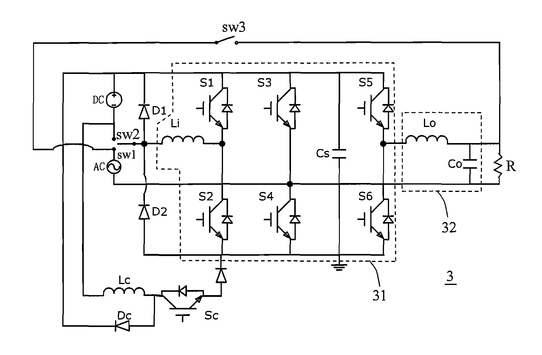
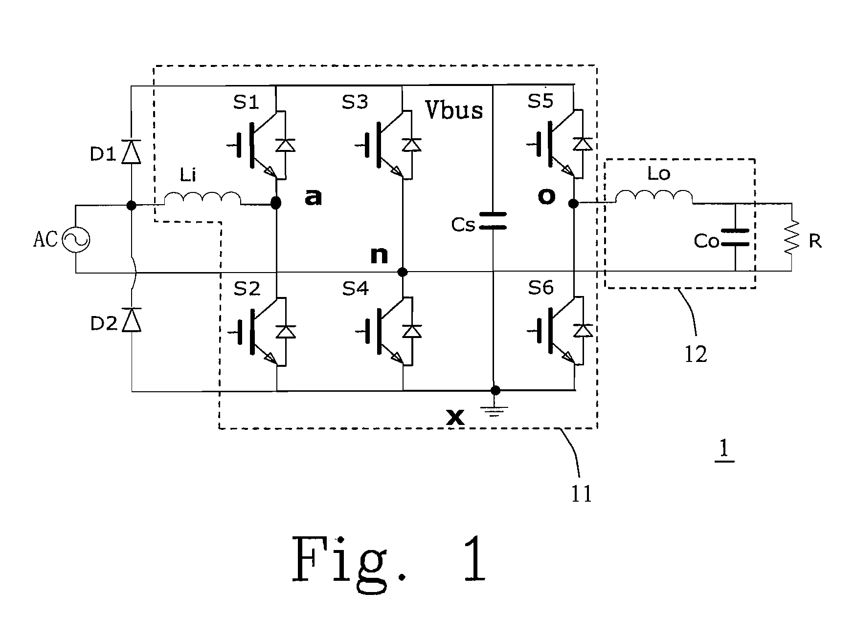
[0039] The present invention will now described more specifically with reference to the following embodiments. Please refer to FIG. 3(a) which is a circuit diagram of a line-interactive uninterruptible power supply apparatus on which the controlling method of the present invention is applied. The numerals of FIG. 3(a) are similar to those of FIG. 1 for the same components. The line-interactive uninterruptible power supply apparatus 3 contains a DC input voltage DC, an AC input voltage AC, a switch set containing diodes D1 and D2, a single-phase AC / AC converter 31, an AC filter 32 containing a filter inductor Lo and a filter capacitor Co, and a load R.

[0040] The single-phase AC / AC converter 31 contains an AC inductor Li, a bus capacitor Cs and three arms. A arm containing switches S1 and S2 is called as a boost arm. A arm containing switches S3 and S4 is called as a common arm. A arm containing switches S5 and S6 is called as a buck arm. Switches SW1, SW2 and SW3 are respectively us...


PUM


Abstract

A method of controlling an uninterruptible power supply apparatus (UPS) is provided. The UPS apparatus includes at least an AC input voltage, a DC input voltage and a single-phase AC / AC converter. The single-phase AC / AC converter includes an AC inductor, a bus capacitor, a boost arm, a common arm and a buck arm. The method includes steps of: controlling the bus voltage to have a DC component and full-wave rectifying component, and setting a bus voltage parameter K so that the bus voltage approaches to a full-wave rectifying voltage when K approaches to 1, wherein 0≦K≦1.

Description

FIELD OF THE INVENTION [0001] The present invention relates to a method of controlling an uninterruptible power supply apparatus, particularly to an uninterruptible power supply of a simple-phase AC / AC converter having three arms. BACKGROUND OF THE INVENTION [0002] Please refer to FIG. 1 which is a circuit diagram of a conventional line-interactive uninterruptible power supply. In FIG. 1, the conventional line-interactive uninterruptible power supply contains an AC input voltage AC, a switch containing two diodes D1 and D2, a single-phase AC / AC converter 11, an AC filter 12 containing a filter inductor Lo and a filter capacitor Co, and a load R. [0003] The single-phase AC / AC converter 11 contains an AC inductor Li, a bus capacitor Cs and three arms. The three arms are respectively a boost arm consisted of a switch S1 and a switch S2, a common arm consisted of a switch S3 and a switch S4 and a buck arm consisted of a switch S5 and S6. [0004] An AC input voltage AC directly provides e...

Claims


Application Information

Patent Timeline
IPC IPC(8): H02J9/00H02M7/5387H02M7/00
CPCH02J9/062
Inventor LU, YAN-SONGTAN, JING-TAOYANG, JIAN-PINGYING, JIAN-PING
Owner DELTA ELECTRONICS INC
Why Eureka
Try Eureka