
Electrochemical apparatus with barrier layer protected substrate

a technology of electrochemical apparatus and substrate, which is applied in the manufacture of secondary cells, electrochemical generators, cell components, etc., can solve the problems of affecting the electrochemical properties of cathodes, cathodes may not fully, capacity, energy, current, power capacity, etc., and achieve the effect of preventing diffusion

Inactive Publication Date: 2008-01-03
SAPURAST RES
View PDF3 Cites 115 Cited by
  • Summary
  • Abstract
  • Description
  • Claims
  • Application Information

AI Technical Summary

Benefits of technology

The patent text discusses the challenges of using thin-film batteries in portable and on-board devices, where the battery needs to be thin enough to fit in the space available while still maintaining its performance. The text highlights the importance of post-deposition annealing, which can improve the crystallinity and electrochemical properties of the battery. However, the high temperatures required for annealing can cause compatibility issues with the substrate materials used to build the battery. The text also mentions the need for chemically inert substrates that do not contaminate the battery materials or affect their performance. The technical effect of the patent text is to provide a solution for improving the crystallinity and electrochemical properties of thin-film batteries without compromising the substrate materials used to build them.

Problems solved by technology

In other cases, unwanted species from the substrate may diffuse into LiCoO2 during the high annealing temperatures and contaminate the positive cathode thereby detrimentally altering its electrochemical properties.
If the annealing temperature is kept sufficiently low to prevent reactions or unwanted diffusion, then the cathode may not fully crystallize, and capacity, energy, current, and power capability, and, in the case of rechargeable batteries, lifetime (number of cycles) may suffer.

Method used


Image

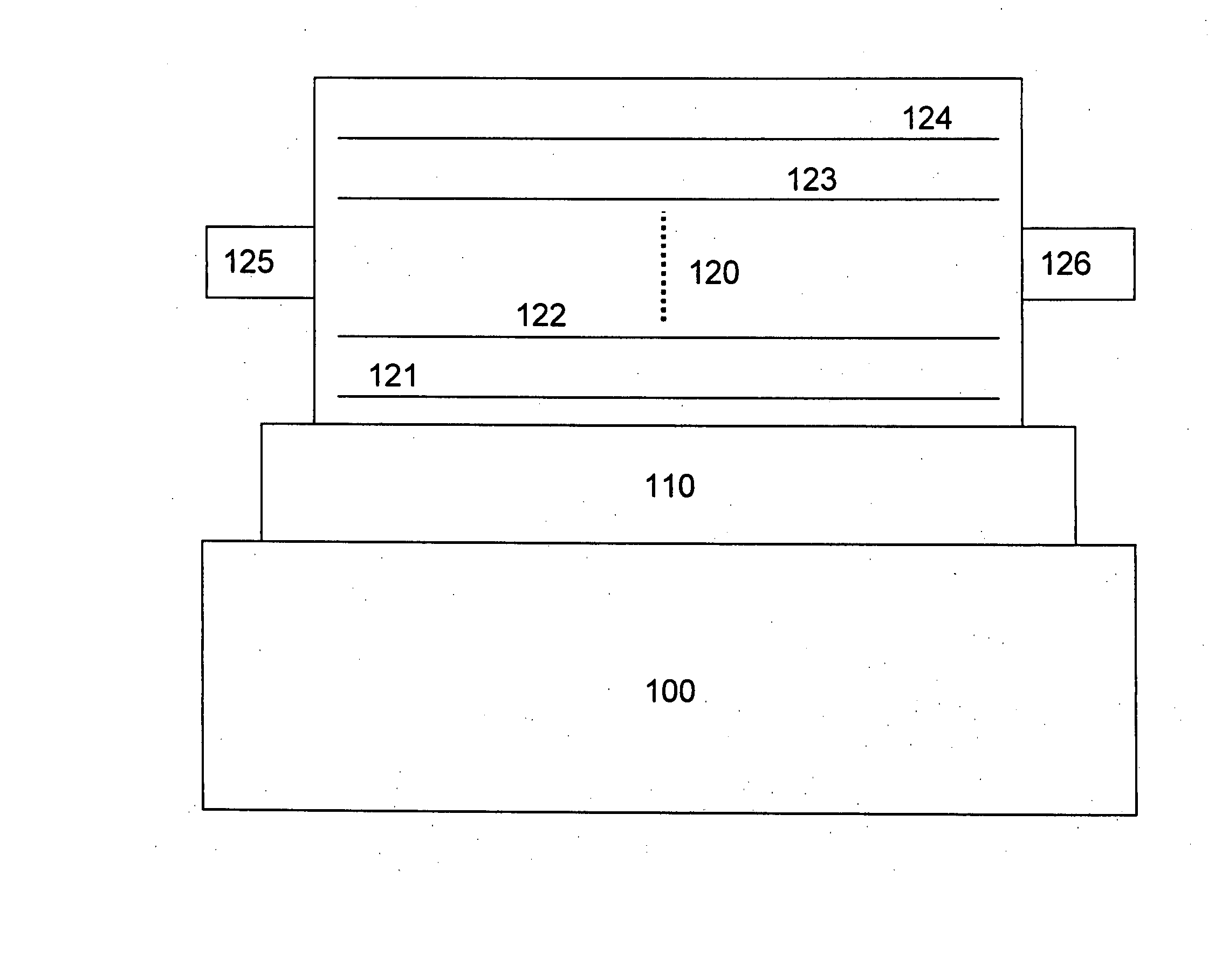
  • Electrochemical apparatus with barrier layer protected substrate
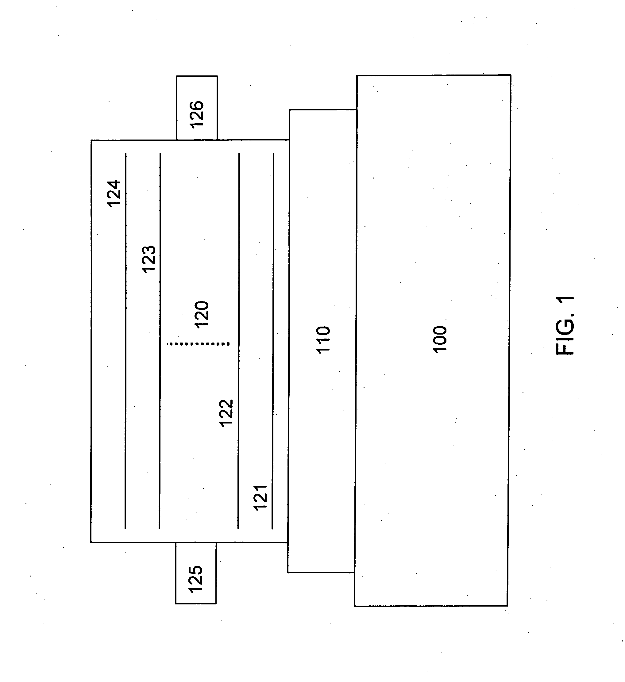
  • Electrochemical apparatus with barrier layer protected substrate
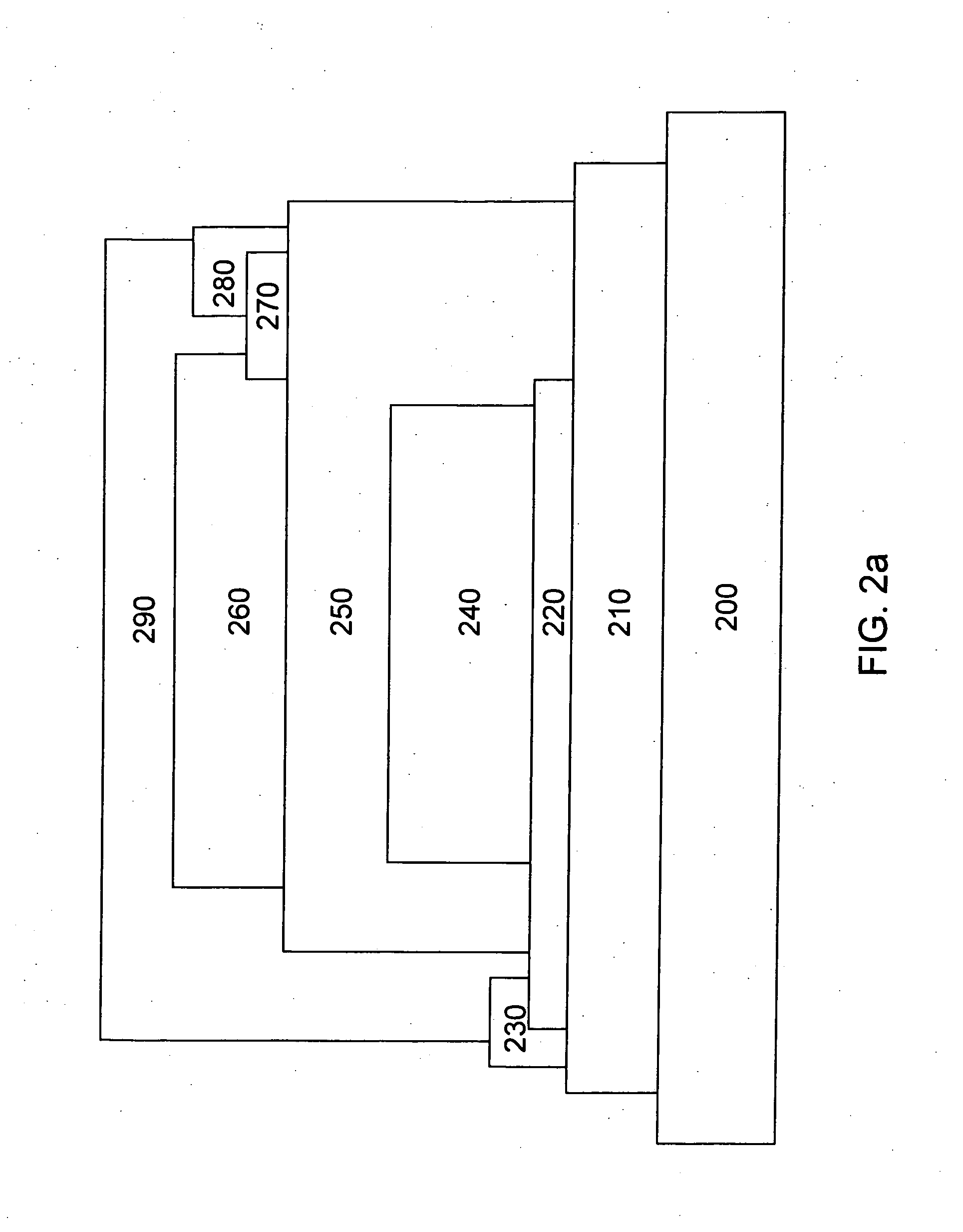
  • Electrochemical apparatus with barrier layer protected substrate

Examples


Embodiment Construction

[0059] It should be understood that this invention is not limited to the particular methodology, protocols, etc., described herein and, as such, may vary. The terminology used herein is for the purpose of describing particular embodiments only, and is not intended to limit the scope of the present invention, which is defined solely by the claims.

[0060] As used herein and in the claims, the singular forms “a,”“an,” and “the” include the plural reference unless the context clearly indicates otherwise.

[0061] All patents and other publications identified are incorporated herein by reference for the purpose of describing and disclosing, for example, the methodologies described in such publications that might be used in connection with the present invention. These publications are provided solely for their disclosure prior to the filing date of the present application. Nothing in this regard should be construed as an admission that the inventors are not entitled to antedate such disclos...


PUM

PropertyMeasurementUnit
thicknessaaaaaaaaaa
thicknessaaaaaaaaaa
temperatureaaaaaaaaaa

Abstract

The present invention relates generally to fabricating well performing thin-film batteries onto metallic substrates, polymeric substrates, and doped and undoped silicon substrates. More specifically, the invention may include fabricating an appropriate diffusion barrier layer between the substrate and the battery part of the present invention that separates said two parts chemically during the entire battery fabrication process and the operation and storage conditions of the electrochemical apparatus during its entire lifetime. In one embodiment of the present invention, thin-film batteries fabricated onto a thin, flexible, stainless steel foil substrate using an appropriate diffusion layer show uncompromised electrochemical performance compared to thin-film batteries fabricated onto ceramic substrates when using a 700° C. post-deposition anneal process for the LiCoO2 positive cathode.

Description

FIELD OF THE INVENTION [0001] The present invention relates generally to the fabrication of lithium-based, solid-state, thin-film, secondary and primary batteries with improved capacity density, energy density, and power density. Flexible form factor and crystalline LiCoO2, LiNiO2, LiMn2O4 cathodes and / or derivative materials may be used. BACKGROUND OF THE INVENTION [0002] The following passage describes the need and evolution of the present invention in view of the background technology in the field of thin film batteries. [0003] Thin-film batteries may be fabricated by sequential vacuum depositions of the layered battery components onto a given substrate in, for example, the following order: positive cathode current collector, positive cathode, negative anode current collector, electrolyte (separator), negative anode, and encapsulation, where the latter may be a lamination process instead of a deposition process step (See, for example, B. Wang et al., Journal of the Electrochemica...

Claims


Application Information

Patent Timeline
Patent Type & Authority Applications(United States)
IPC IPC(8): H01M6/02B05D5/12H01M6/00
CPCH01M2/1094H01M6/40H01M10/0436Y02E60/122H01M10/0562H01M10/0585H01M2004/021H01M10/052Y02E60/10H01M50/24
Inventor NEUDECKER, BERND J.MCGRAW, JEANNE M.EMERSON, BRIAN K.SNYDER, SHAWN W.
Owner SAPURAST RES
Learn More