Fuel Cell And Fuel Cell Separator
a technology of fuel cell and separator, which is applied in the direction of cell components, electrochemical generators, cell component details, etc., can solve the problems of lowering heat conductivity and electrical conductivity
- Summary
- Abstract
- Description
- Claims
- Application Information
AI Technical Summary
Benefits of technology
Problems solved by technology
Method used
Image

Examples
first embodiment
A. Structure of Fuel Cell Stack in First Embodiment of the Invention
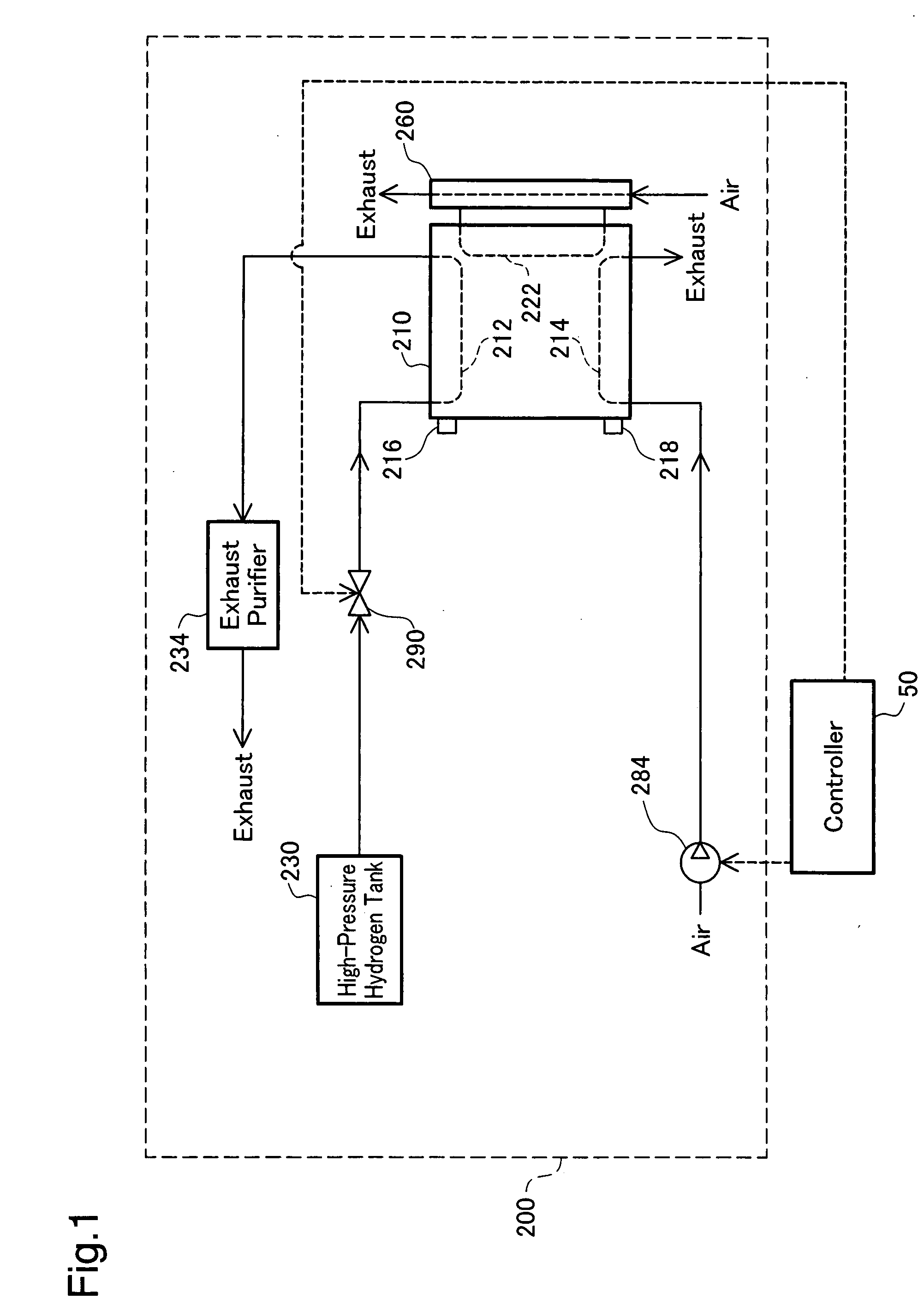
[0083]FIG. 1 schematically illustrates the configuration of a fuel cell system 200 including a fuel cell stack 210 in one embodiment of the invention. The fuel cell stack 200 includes, in addition to the fuel cell stack 210, a high-pressure hydrogen tank 230 that stores a fuel gas (hydrogen gas) for a supply to the fuel cell stack 210, a fuel gas supply valve 290 that is operated to regulate the supply of the fuel gas, an exhaust purifier 234 that purifies an anode off gas as an exhaust from the fuel cell stack 210, an air supply pump 284 that is actuated to introduce a supply of oxidizing gas (the air) to the fuel cell stack 210, and a heat exchanger 260 that cools down the fuel cell stack 210. In the specification hereof, the terminology ‘reactive gas’ represents at least one of the fuel gas and the oxidizing gas.
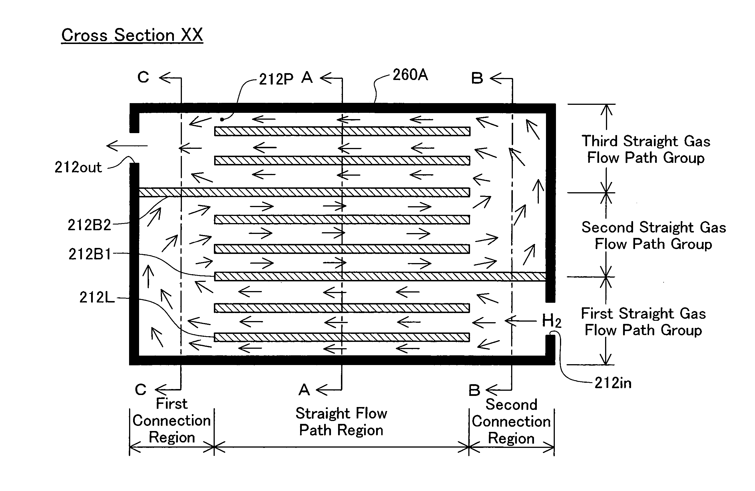
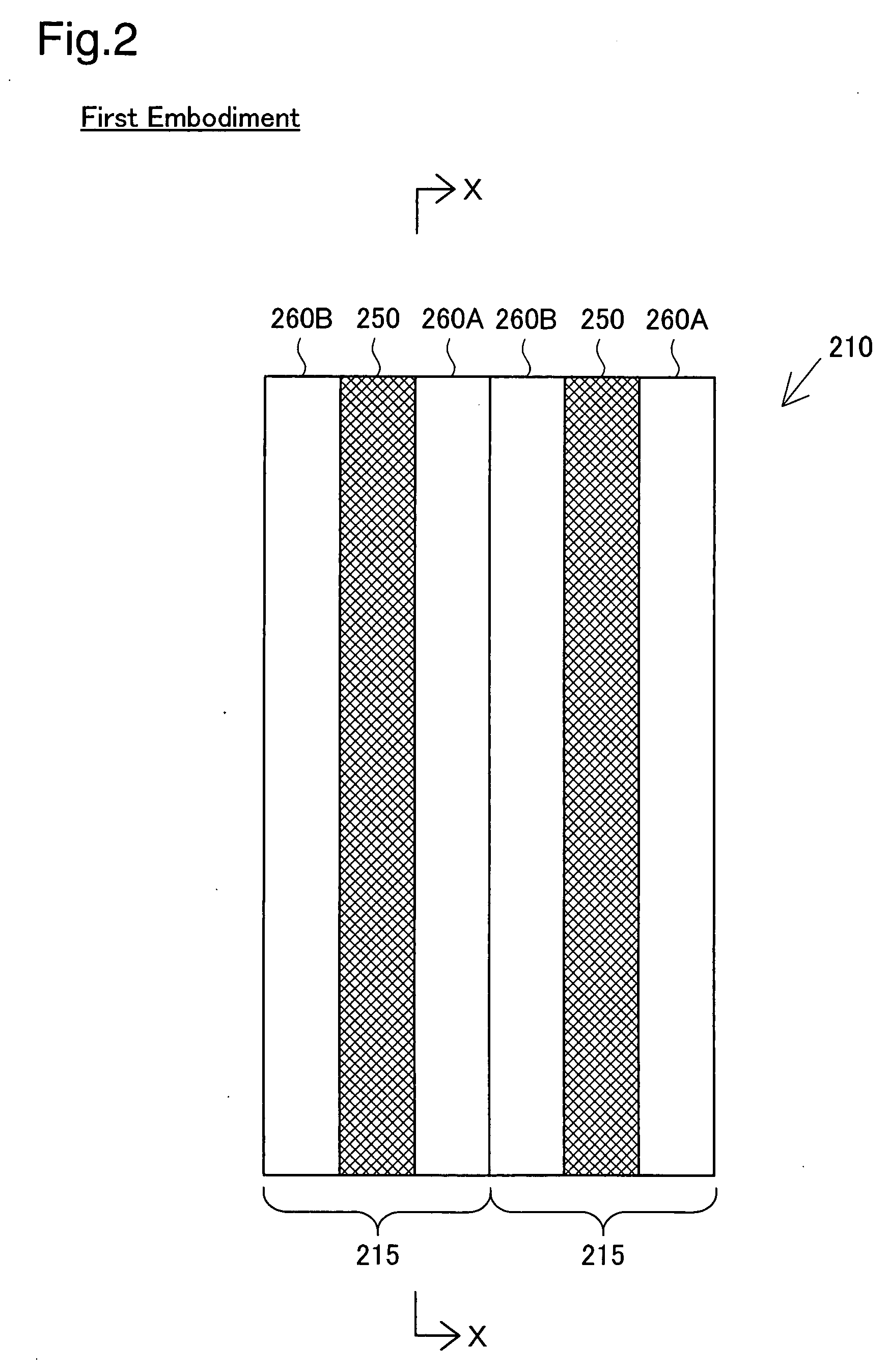
[0084] The fuel cell stack 210 has an anode gas flow path 212, a cathode gas flow path 214, a refrige...
second embodiment
B. Structure of Fuel Cell Stack in Second Embodiment of the Invention
[0100]FIG. 5 shows an anode gas flow path pattern 213P on a separator 261A in a second embodiment of the invention. The primary different from the anode gas flow path pattern 212P of the first embodiment is that the anode gas flow path pattern 213P of the second embodiment has multiple projections 261C protruded into the anode gas flow path.
[0101] The multiple projections 261C are provided to prevent the potential blockage of the anode gas flow due to condensation of the anode gas in the first connection region and in the second connection region. The condensation of the anode gas is ascribed to the lowered flow rate of the anode gas in the first and second connection regions and resulting liquefaction of the water content included in the anode gas. The flow rate of the anode gas is lowered by conversion of the kinetic energy into the pressure energy in the flow of the anode gas from the straight gas flow path gro...
third embodiment
C. Structure of Fuel Cell Stack in Third Embodiment of the Invention
[0105]FIG. 6 shows an anode gas flow path pattern 214P on a separator 262A in a third embodiment of the invention. The primary differences from the anode gas flow path pattern 213P of the second embodiment are: (1) the thickness of gas flow path parting beams 262B in the gas flow path pattern 214P of the third embodiment is about 1.5 times as much as the thickness of the straight gas flow path forming beams 212L (see FIG. 6(a)); and (2) the gas flow path pattern 214P of the third embodiment has a refrigerant control weir 262D protruded in the refrigerant flow path at a position in the vicinity of a straight refrigerant flow path formed as the reverse of the gas flow path parting beam 262B (see FIGS. 6(b) and 6(c)).
[0106] As shown in FIG. 6(a), the gas flow path parting beams 262B have the 1.5-fold thickness of the straight gas flow path forming beams 212L, in order to prevent the potential gas leakage from the firs...
PUM
 Abstract
Description
Claims
Application Information
 - R&D
- Intellectual Property
- Life Sciences
- Materials
- Tech Scout
- Unparalleled Data Quality
- Higher Quality Content
- 60% Fewer Hallucinations
Browse by: Latest US Patents, China's latest patents, Technical Efficacy Thesaurus, Application Domain, Technology Topic, Popular Technical Reports.
© 2025 PatSnap. All rights reserved.Legal|Privacy policy|Modern Slavery Act Transparency Statement|Sitemap|About US| Contact US: help@patsnap.com