
Process for Neutron Interrogation of Objects in Relative Motion or of Large Extent

a technology of object relative motion and neutron radiation, applied in the direction of neutron radiation measurement, engine lubrication, liquid/fluent solid measurement, etc., can solve the problems of reduced operational life between servicing sessions, reduced analysis and reduction to practice, and reduced use efficiency, etc., to achieve easy removal of extraneous noise effects, minimize cross-sectional blockage, and high speed

Inactive Publication Date: 2007-12-27
SVED JOHN
View PDF1 Cites 30 Cited by
  • Summary
  • Abstract
  • Description
  • Claims
  • Application Information

AI Technical Summary

Benefits of technology

[0058] Embodiments of the present invention seek to provide neutron interrogation apparatus of high reproducibility in mass produced embodiments.
[0076] A fourth aspect of the present invention is the utilization for relatively high speed and high throughput rate industrial applications. In particular the food industry with is very diverse range of products has a need for detection of foreign objects and substances that may contaminate food products. The flow rate of food product units has a wide range. Most readers will imagine the rate of production of packaged food. An embodiment which can cope with such flow rates is disclosed as a variation of the above described embodiment which are configured for scanning a stream of highly variable objects. If the objects are highly uniform, as is the case for a food production line, the detection of anomalous elemental or isotopic ratios can be recognized at a lower threshold of acquired statistical data. The effective neutron dose is correspondingly reduced. The matching of scan data with the object being scanned through the system is again achieved by a sensor data multiplexing sub-system. The embodiment is also able to deal with bulk food material such as frozen vegetables for real time detection of contaminants such as non-biological minerals, chemicals, elements and biological origin parasites such as worms. The vegetable units are already frozen by immersion in liquid nitrogen. The mass flow rate is approximately 300 kg per hour. This corresponds to a vegetable unit flow rate of 30,000 to 300,000 per hour. The size and traverse time may vary depending on the type and size range of the vegetables. If present, the contaminants or foreign bodies are distributed inside the frozen vegetable units. Detection must be fast enough to actuate a rejection mechanism for removal of the suspect vegetable unit. The high speed will require scanning and recognition of approximately 8-80 vegetable units per second! The utilization of the present invention in a linear longitudinal traverse configuration embodiment, as described above, is one option for the lower flow rate. Another embodiment described below can cope with the higher rate.

Problems solved by technology

As the reaction rate is increased there is a reduction of operational life between servicing sessions.
Such analysis and reductions to practice may be compromised or constrained by available materials and equipment.
Also to be incorporated into the design process are the unwanted but present secondary emissions from shielding and instrumental limitations and sources of electronic noise.
Another design factor is the counting limitation of detector systems where the frequency of gamma or neutron events that can be correctly resolved and processed into electronic event energy information will impose a practical upper limit on the impinging flux of neutrons.
A common characteristic in the above mentioned examples is that the flow rate of items to be scanned is relatively high and indeed too high for the neutron interrogation systems that have been deployed into practical operation.
A standard commercially available gamma spectrum detection system can find concealed explosives in baggage and it is very difficult to shield out the neutrons without raising suspicion.
From the industrial customer point of view, whilst neutrons are attractive they are hard to produce on demand conveniently or cheaply.
The radionuclide source of neutrons has been the lowest cost source of neutrons but the inability to switch off the source has imposed difficult operational safety requirements.
Solving these design requirements for practical neutron applications systems has added to the cost of manufacture and the cost of operation.
There is a recurring cost associated with procurement, safety monitoring and ultimate authorized disposal of the radioisotope neutron source capsules.
The operational life of the device is very short prior to its total destruction within the nuclear weapon.
These sealed tube devices have been commercialized but have found almost no acceptance in industrial settings where the requirement for economic life cycle costs have been too severe for that technology.
The cost of exchanging of a sealed tube device, which includes authorized recovery of the tritium gas, is prohibitively high.
A further problem with the sealed tube neutron generator is that the obtainable lifetime is achieved by a combination of compromises.
The costs of manufacturing have forced sealed tube neutron generator manufacturers to modify existing weapons-derived devices.
A further problem with the sealed tube neutron generators that utilize the D-T fusion reaction is that the D-T fusion neutron energy is 14.1 MeV.
While D-T 14 MeV neutrons are useful because they are more penetrating than 2.1 MeV neutrons, and while the higher energy enables certain interactions with certain elements such as oxygen, there are also problems.
The moderation and collimation of a range of neutron energies is obviously more difficult than for mono energy neutrons.
Sealed tube devices do provide mono energy neutrons but suffer from unreliability of the neutron output as do the accelerator spallation neutron sources.
The solid targets that these devices use suffer from altered characteristics due to the damage they incur through use.
The pulse mode duty cycle may range from minutes or seconds of ON time and similar intervals of OFF time to milli-, micro- and even nanoseconds pulse duration It is not necessary, cost effective or perhaps not practical to offer the entire pulsing duty cycle range in every neutron generator.
The implementation of mechanical shutters to make 252Cf into a pseudo-pulsed neutron source is not practical nor cost effective.
This has undesirable consequences for the efficiency of the detection of gamma photons arising from the neutron interactions.
Optimization of the gamma detector configuration may not be sufficient or cost effective.
However, it is more problematic for a neutron application system that would use two neutron generator devices.
This may reduce the effectiveness of the land mine detector system.
Damage to the system by an exploding land mine is a further difficulty.
However, the use of several conventional sealed tube neutron generators would be a significant fraction of the total system cost.
Further complexity would arise from the control problem associated with matching of output of multiple sealed tube units.
Such a system is considered to be a very expensive option due to the inherent complexity and reliability concerns.
The sealed tube neutron generator technology is inherently age-limited by the unavoidable erosion of the solid target.
The incident high energy deuterons have the effect of causing sputter erosion of the target.
The use of voltages near 100 kilovolts results in a short circuit condition as the metallic film builds up.
Even before this ultimate failure mode, the highly localized beam causes a hot spot and associated gas depletion within the target.

Method used


Image

  • Process for Neutron Interrogation of Objects in Relative Motion or of Large Extent
  • Process for Neutron Interrogation of Objects in Relative Motion or of Large Extent
  • Process for Neutron Interrogation of Objects in Relative Motion or of Large Extent

Examples


Embodiment Construction

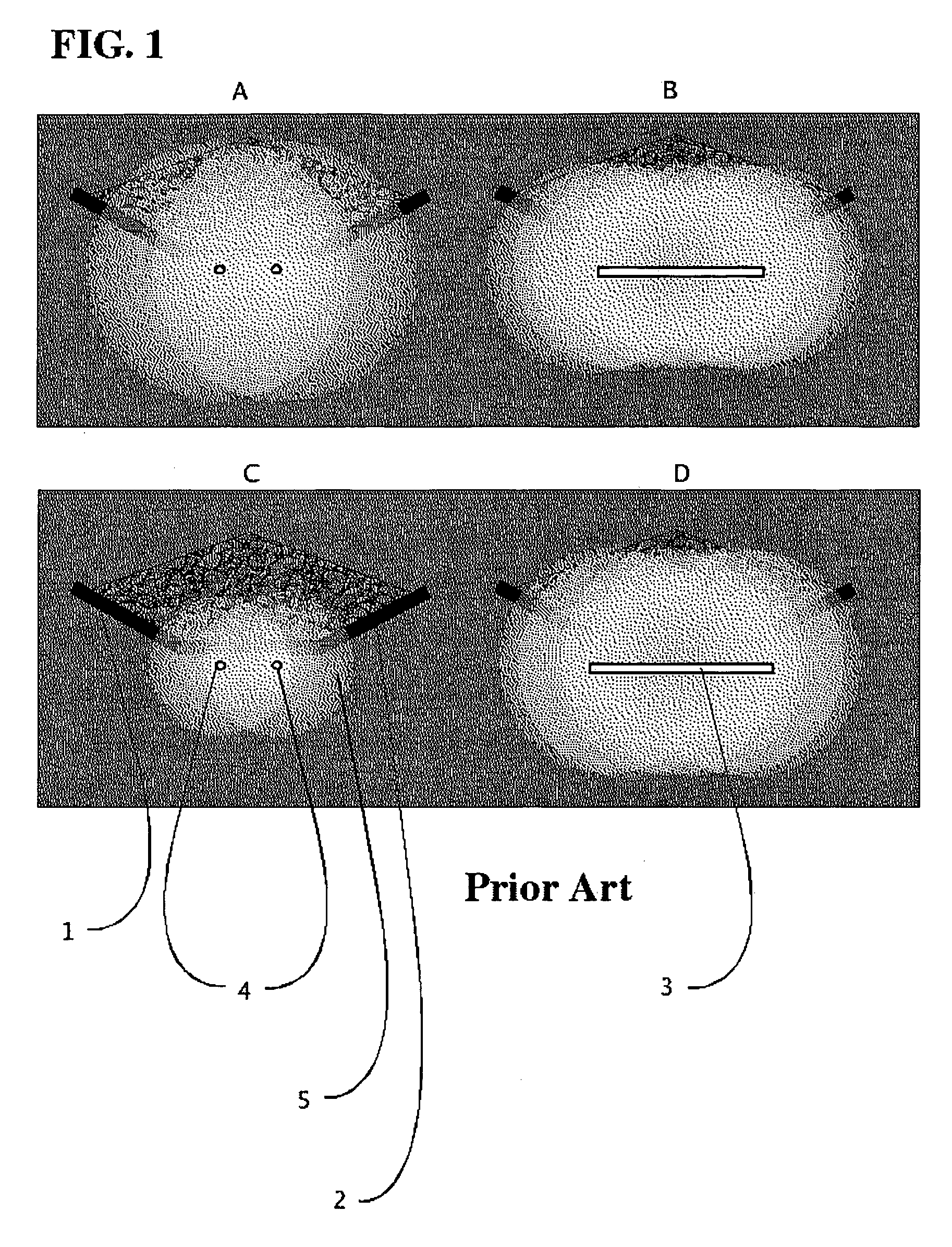
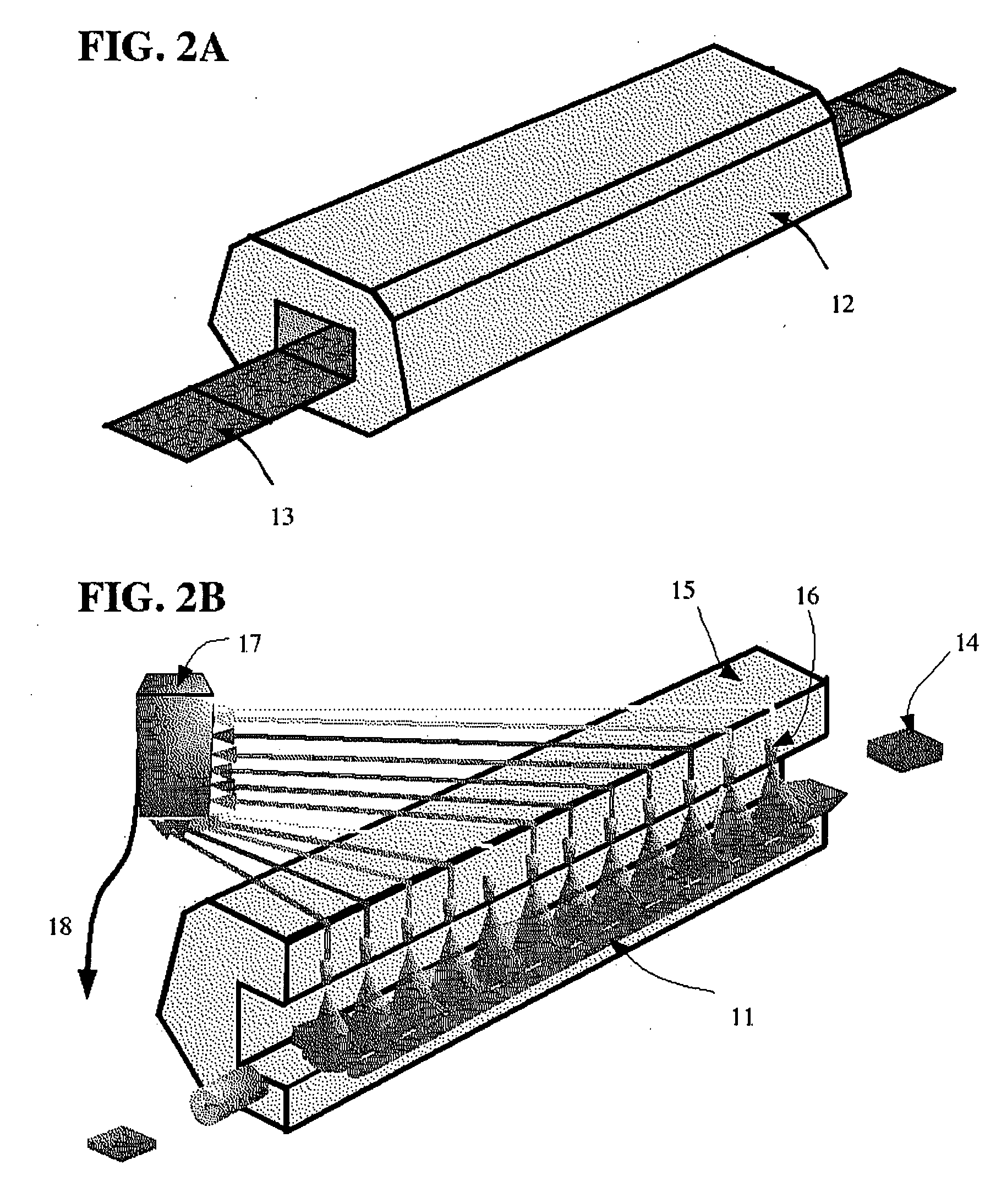
[0089] The present invention makes use of the length characteristic or more generally the three dimensional topology of neutron generators which are able to provide this feature to teach utilization in example embodiments which have not been disclosed in prior art. The applicable neutron generators have a non-point-like zone of neutron emission. With point-like neutrons sources such as radionuclides or the well known neutron generators that have been available prior to 2003 emission field characteristics similar to line sources have been achieved by the use of multiple point sources as shown in FIG. 1A where a conveyor belt 1 or similar mechanism carrying bulk material 2 is irradiated at a defined location by a flux of neutrons for an elemental analysis technique. The requirement for a line source has been implicit since the introduction by manufacturers of online mineral analysis systems with an array of point sources. The utilization of such a line source 3 is illustrated in FIG. ...


PUM

PropertyMeasurementUnit
diameteraaaaaaaaaa
lengthaaaaaaaaaa
lengthaaaaaaaaaa

Abstract

The invention relates to the fact that a common industrial neutron interrogation screening requirement is that a high throughput rate be accommodated by the screening system. The accumulation of elemental abundance ratio spectral data to minimize statistical uncertainty is a function of the neutron flux passing through the subject. If the subject passes through a neutron beam, with a strictly limited time window for exposure, the flux must be sufficient to accumulate the required statistics. The level of neutron flux necessary may exceed the cost effective limits of the selected neutron source means. Exposure time window dilation is disclosed through a class of system configurations which become practical for reduction to practice by utilization of linear neutron source topology neutron generators. This disclosure is concerned with example embodiments which utilize the length, width, thickness and segmentation of the source emission zone within an appropriate neutron source.

Description

FIELD OF THE INVENTION [0001] This disclosure teaches about a class of configurations of neutron source, moderator, collimator, shielding, the subject or a plurality of subjects to be scanned and the traverse kinematics which exploit the linear source geometry in order to add a time dilation design variable to the optimal design of neutron interrogation systems or general neutron irradiation systems. [0002] The availability of neutron sources which are elongated in one or two dimensions so as to be defined as functional line or plane sources enables many commonly proposed application system geometries. Several line source like neutron generators have been proposed including the reference prior art invention of which this disclosure is a class of embodiments. Neutron interrogation techniques are applied in appropriate laboratories and in some industries in a on-line or in-line situation as a contact-less measurement technique. A common industrial requirement is that a short scanning ...

Claims


Application Information

Patent Timeline
Patent Type & Authority Applications(United States)
IPC IPC(8): G01N23/00
CPCG01T3/00
Inventor SVED, JOHN
Owner SVED JOHN
Learn More