
Means and Method for Detection of Blood Leakage from Wounds

a technology for wounds and blood leakage, applied in the field of wounds blood leakage detection methods and means, can solve problems such as bleeding, patient may have lost a substantial volume of blood, wounds caused,

Inactive Publication Date: 2007-12-20
REDSENSE MEDICAL MALTA
View PDF13 Cites 50 Cited by
  • Summary
  • Abstract
  • Description
  • Claims
  • Application Information

AI Technical Summary

Benefits of technology

[0009] In a monitoring state, in which the fibre wall of the blood detection zone is in dry contact with air and / or solid materials, the transport of light in the fibre will not be affected. In an alarm state, in which the fibre wall of the blood detection zone is contacted with blood, the transport of light in the fibre will be notably and even substantially reduced, such as by 10% or 20% or 35% and even up to about 50% or more within a short period of time such as ten seconds and even one second. The reason for this reduction is the change of (inner) reflectance of at a portion of the fibre wall by contact with blood which is a medium of higher refractive index than the fibre material. Specifically the change is from practically total reflection of light conducted by the fibre at the fibre wall in a monitoring state to that of reduced reflection at fibre wall portions that are in contact with blood in an alarm state.

Problems solved by technology

A well-recognised problem in hospital care is that wounds caused by surgery or accidents, in spite of having been properly closed and dressed, may start to bleed again.
In the meantime the patient may have lost a substantial volume of blood.
This will no doubt have a detrimental effect on his or her recovery.
Another problem of similar kind is quite frequently seen in blood dialysis.
The adhesive tape may accidentally come off and the cannula withdrawn.
Inevitably this results in immediate bleeding, which may be quite severe.
If the bleeding is not noticed and stopped at once the patient may loose a large volume of blood.
Since dialysis patients are usually anaemic, they are particularly affected by such a loss.
Due to the pressure drop in the venous needle a loosening thereof cannot be monitored easily in a corresponding manner.

Method used


Image

  • Means and Method for Detection of Blood Leakage from Wounds
  • Means and Method for Detection of Blood Leakage from Wounds
  • Means and Method for Detection of Blood Leakage from Wounds

Examples


Embodiment Construction

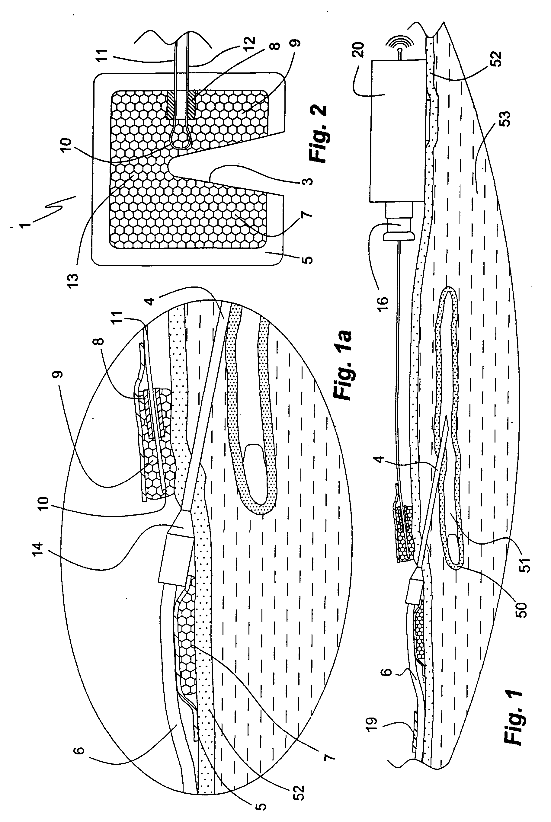
[0023] The apparatus of the invention shown in the Figures comprises a single-use disposable flexible patch 1 of about rectangular form. In the Figures it is shown disposed around an infusion cannula 4 inserted through the skin 52 and tissue 53 into a vein 50 in the forearm of a patient. The tip 4′ of the cannula 4 is located in the lumen 51 of vein 50. The patch 1 surrounds the cannula 4 at the punctuation site by means of a wedge-formed incision 3 in the patch 1. The incision 3 defines two opposite wings 7, 9 that extend from the central portion of the patch 1. At its distal end the cannula 1 is mounted in a short polycarbonate tube 14 provided with wings (not shown), which stops further insertion of the cannula 4 into the vein 50. From the polycarbonate tube 14 two wings (not shown) extend radially. A flexible tube 6 by which purified blood is adduced from a hemodialysis apparatus (not shown) is in fluid communication with the cannula 4 lumen; neither shown is the corresponding a...


PUM


Abstract

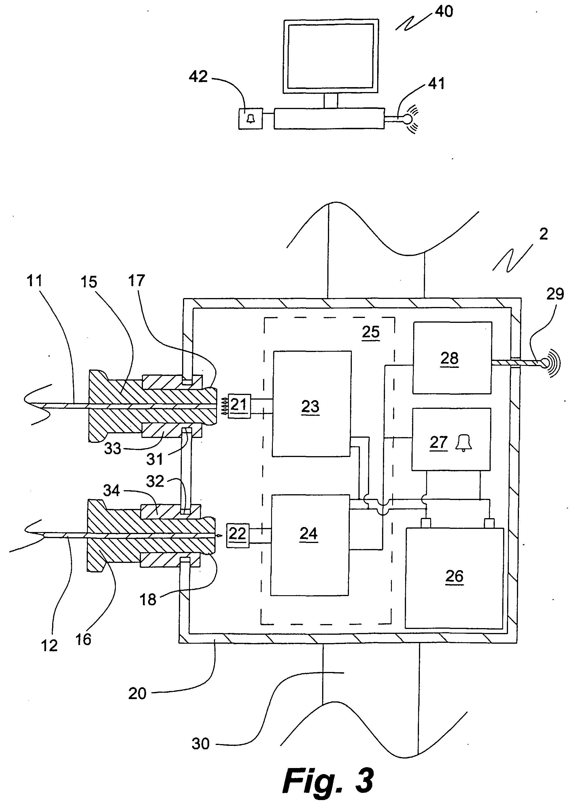
An optical fibre through which light passes is used for detecting blood leakage from a wound. The fibre may be comprised by a blood leakage detection apparatus having a light source and a photo detector in radiative communication with the respective ends of the fibre and producing an electrical signal in response to the light detected, photo detector signal amplifying means, means for detecting changes in the amplified signal over time, and alarm means, wherein a decrease in signal strength during a selected time period activates the alarm means; a corresponding method of detecting blood leakage; a device for use with the apparatus of the invention comprising the optical fibre thereof provided with coupling means at its ends and a patch of blood absorbing material.

Description

FIELD OF THE INVENTION [0001] The present invention relates to a method and means for detecting blood leakage from wounds, and to a corresponding use of the means. BACKGROUND OF THE INVENTION [0002] A well-recognised problem in hospital care is that wounds caused by surgery or accidents, in spite of having been properly closed and dressed, may start to bleed again. Due to the dressing by which the wound is covered or due to the patient being unconscious or otherwise unable to recognise the bleeding, it is only noticed by the staff and taken care of after a while. In the meantime the patient may have lost a substantial volume of blood. This will no doubt have a detrimental effect on his or her recovery. [0003] Another problem of similar kind is quite frequently seen in blood dialysis. In a life saving treatment patients with impaired or non-existing renal function purify their blood from salts, urea and other metabolic degradation products on a regular basis, such as two or three tim...

Claims


Application Information

Patent Timeline
IPC IPC(8): A61B5/026A61B5/00G01NH04B10/25
CPCA61B5/0059A61B5/026G01N33/49H04B10/25H04B10/11A61B5/0261
Inventor ENGVALL, DANIELJONSSON, LENNARTKARLSSON, PER-OLOFRUTGERSSON, LARSSVENSSON
Owner REDSENSE MEDICAL MALTA
Learn More