
Refrigerant cycle device and heat-exchanger integrated unit with temperature sensor for the same

Inactive Publication Date: 2007-12-20
DENSO CORP
View PDF8 Cites 34 Cited by
  • Summary
  • Abstract
  • Description
  • Claims
  • Application Information

AI Technical Summary

Benefits of technology

[0009]In view of the foregoing problems, it is an object of the present invention to provide a refrigerant cycle device in which a frost prevention control can be effectively performed.
[0010]It is another object of the present invention to provide a heat-exchanger integrated unit for a refrigerant cycle device, in which a temperature sensor used for a frost prevention control can be easily attached at a suitable position of a heat exchanger.
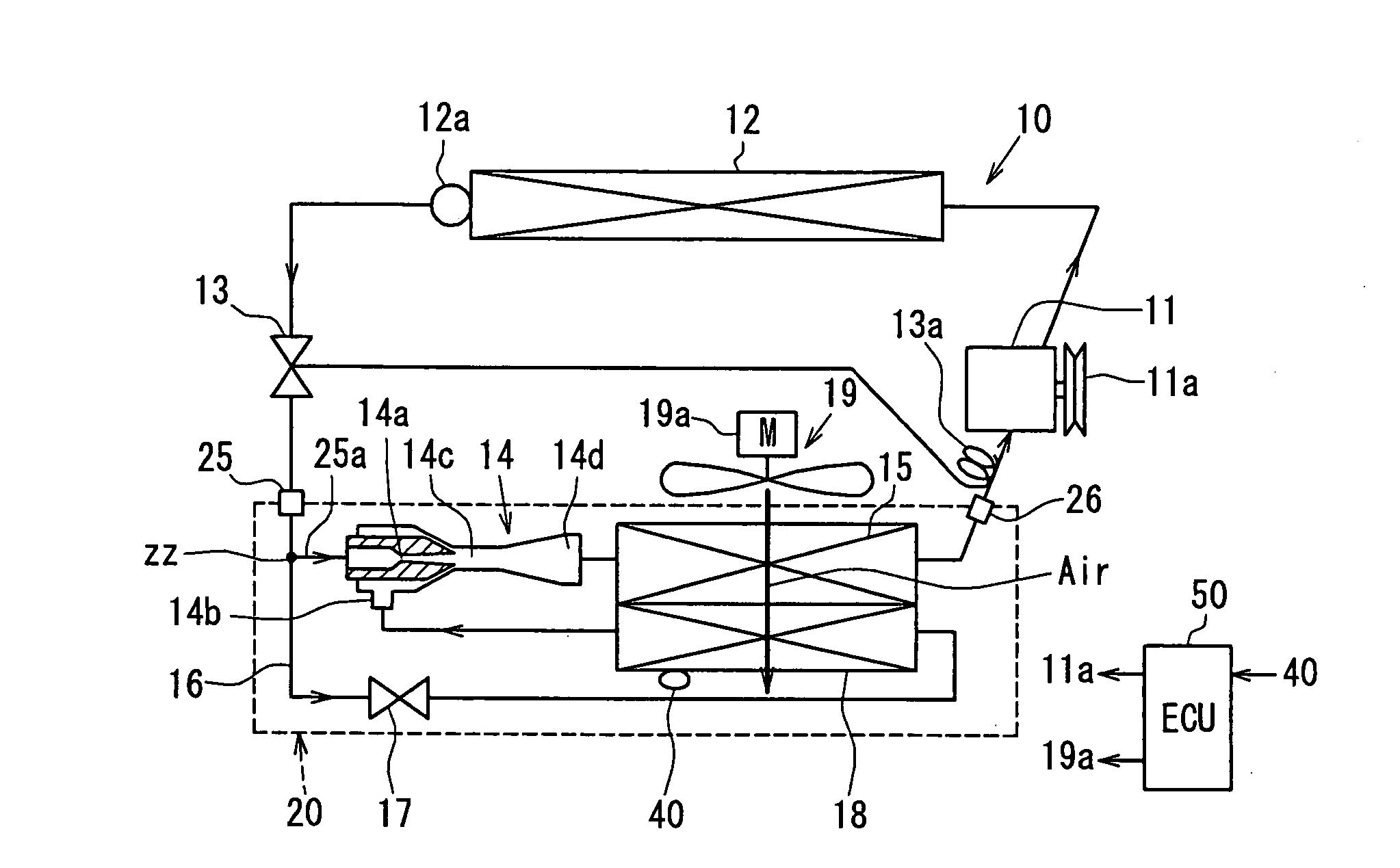
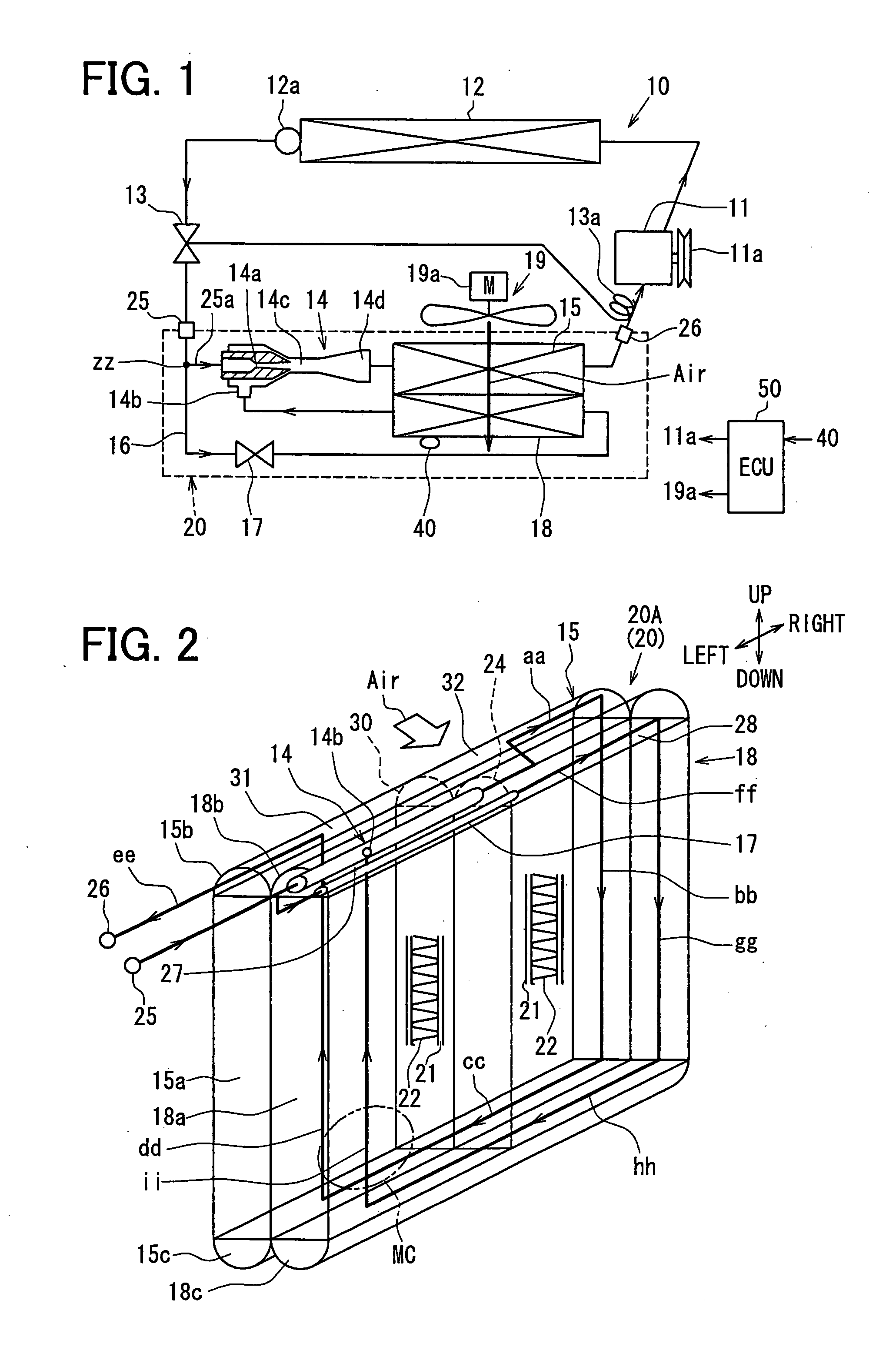
[0011]According to a first example of the present invention, a refrigerant cycle device includes a compressor for sucking and compressing refrigerant, a radiator located to cool high-pressure refrigerant discharged from the compressor, a refrigerant adjusting unit located to adjust a refrigerant amount flowing from the radiator to a downstream side such that a super-heating degree of refrigerant to be sucked to the compressor approaches to a predetermined degree, an ejector that includes a nozzle portion for decompressing refrigerant flowing from the refrigerant adjusting unit and a refrigerant suction port from which refrigerant is drawn by a high-speed refrigerant stream jetted from the nozzle portion, a refrigerant branch passage that is branched from an upstream side of the nozzle portion in a refrigerant flow such that refrigerant flows into the refrigerant suction port through the refrigerant branch passage, a first heat exchanger disposed to evaporate refrigerant flowing out of the ejector, a second heat exchanger disposed in the refrigerant branch passage to evaporate refrigerant to be drawn into the refrigerant suction port, a temperature sensor located to detect a temperature so as to detect a frost in the second heat exchanger, and a controller which performs a frost prevention control to reduce the frost in the second heat exchanger in accordance with the temperature detected by the temperature sensor. Accordingly, it is possible to reduce and prevent frost generated on the second heat exchanger when being used as an evaporator. Furthermore, because the refrigerant adjusting unit is located to adjust a refrigerant amount flowing from the radiator to a downstream side such that a super-heating degree of refrigerant to be sucked to the compressor approaches to a predetermined degree, operation efficiency of the refrigerant cycle device can be effectively improved.
[0013]The controller can reduces a discharge capacity of refrigerant discharged from the compressor during the frost prevention control, or can stop operation of the compressor during the frost prevention control. Furthermore, the temperature sensor can be located to detect a temperature of air immediately after passing through the second heat exchanger, or can be located to detect a temperature of one of fins and tubes of the second heat exchanger. Furthermore, the predetermined position may be set close to the lower tank.
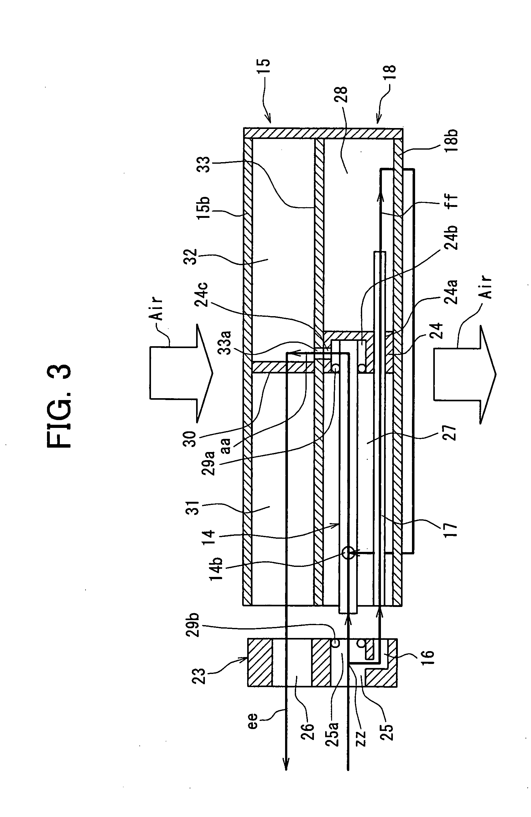
[0014]According to another example of the present invention, a heat-exchanger integrated unit for a refrigerant cycle device includes a heat exchanger for evaporating refrigerant, an ejector that includes a nozzle portion for decompressing refrigerant and a refrigerant suction port from which refrigerant from the heat exchanger is drawn by a high-speed refrigerant flow jetted from the nozzle portion, and a temperature sensor for detecting a temperature so as to detect a frost in the heat exchanger. Furthermore, the temperature sensor is located in the heat exchanger at a predetermined position at which refrigerant flows upwardly from below. Therefore, when the heat exchanger is used as an evaporator, frost generated on the heat exchanger can be suitably reduced by using the temperature detected by the temperature sensor.
[0015]According to another example of the present invention, a heat-exchanger integrated unit for a refrigerant cycle device includes a first heat exchanger located to perform heat exchange between refrigerant and a heat-exchanging medium, a second heat exchanger located downstream from the first heat exchanger in a flow direction of the heat-exchanging medium to perform heat exchange between refrigerant and the heat-exchanging medium flowing from the first heat exchanger, and a temperature sensor located to detect a temperature of the second heat exchanger so as to detect a frost in the second heat exchanger. Furthermore, the first heat exchanger is located to evaporate refrigerant flowing out of an ejector of the refrigerant cycle device, and the second heat exchanger has at least a suction-side heat exchanging portion that is located to evaporate refrigerant to be drawn into a refrigerant suction port of the ejector, from which refrigerant is drawn into the ejector by a high-speed refrigerant stream jetted from the nozzle portion. Because the temperature sensor is located to detect the temperature of the second heat exchanger having a refrigerant temperature lower than that of the first heat exchanger, front can be easily detected using the temperature sensor, thereby effectively reducing and preventing front generated on the second heat exchanger.

Problems solved by technology

Furthermore, in a conventional vapor-compression refrigerant cycle device, when a load to be cooled is small and the temperature of an evaporator is decreased, frost (frosting) occurs on the evaporator.
As a result, a cooling function is not performed effectively.
However, the distribution of refrigerant and air velocity always becomes nonuniform in the evaporator.
At this time, the higher the temperature of a detection point of the temperature sensor, the more the timing of stopping the compressor is delayed, resulting in an excess amount of supply of the refrigerant, which leads to frosting of the evaporator.
Accordingly, air cannot flow downwind smoothly due to the frost, and thus the cooling cannot be performed sufficiently.
In this case, the air temperature sensor senses high air temperature with the formation of the frost, and continues rotating the compressor, which may lead to breakage of the cycle or failure of the compressor.
Although the fin temperature sensor can control such a condition, the cycle cannot be activated until the frosted part is melted, resulting in decrease in cooling operating efficiency.

Method used


Image

  • Refrigerant cycle device and heat-exchanger integrated unit with temperature sensor for the same
  • Refrigerant cycle device and heat-exchanger integrated unit with temperature sensor for the same
  • Refrigerant cycle device and heat-exchanger integrated unit with temperature sensor for the same

Examples


first modification

(First Modification)

[0111]FIG. 10 shows an integrated unit 20B (20) of the first modification.

[0112]As shown in FIG. 10, a separator 15e is disposed in the upper tank portion 15b of the first evaporator 15 to partition the inner space of the upper tank portion 15b into a left inner space C′ and a right inner space D′ such that the left space C′ occupies about one third of the inside of the upper tank portion 15b and the right space D′ occupies about two thirds thereof. A separator 15f is disposed in the lower tank portion 15c of the first evaporator 15 to partition the inner space of the lower tank portion 15c into a left inner space E′ and a right inner space F′ such that the left space E′ occupies about two thirds of the inside of the lower tank portion 15c and the right space F′ occupies about one third thereof.

[0113]Separators 18e and 18f are disposed in the upper tank portion 18b of the second evaporator 18 to partition the inside of the upper tank portion 18b into about three ...

second modification

(Second Modification)

[0127]In the above-mentioned first modified example, the ejector-type refrigerant cycle device 10 using the integrated unit 20B has been explained. However, in the second modified example, an integrated unit 20C (20) shown in FIG. 11 is used for the ejector-type refrigerant cycle device 10. FIG. 11 is a perspective view showing an outline of the entire structure of the integrated unit 20C, in which the basic structures of the first evaporator 15 and the second evaporator 18 are similar to those of the first modified example.

[0128]The integrated unit 20C of FIG. 11 differs from the integrated unit 20B of the first modified example in arrangement and positioning of the separators disposed in the tank portions 15b to 18c, as well as in arrangement and positioning of the ejector 14, and thus in the refrigerant flow path. Ah shown in FIG. 11, a separator 15e′ is disposed in the upper tank portion 15b of the first evaporator 15 to partition the inner space of the uppe...

third modification

(Third Modification)

[0138]In the above-mentioned examples, the ejector-type refrigerant cycle device 10 employing the integrated unit 20A, 20B, 20C has been explained. However, in the third modified example, an integrated unit 20D (20) shown in FIG. 12 is used for the ejector-type refrigerant cycle device 10. FIG. 12 is a perspective view showing an outline of the entire structure of the integrated unit 20D. Also in the integrated unit 20D, the ejector 14, the first and second evaporators 15 and 18, and the temperature sensor 40 are integrally constructed, like the integrated unit 20B, 20C.

[0139]The basic structures of the first and second evaporators 15 and 18 of the integrated unit 20D are the same as those of the first or second modified example. The integrated unit 20D differs from the integrated unit 20B, 20C in arrangement and positioning of the separators disposed in the tank portions 15b to 18c and in arrangement and positioning of the ejector 14. Thus, the third modified ex...


PUM


Abstract

A refrigerant cycle device includes an ejector having a nozzle portion for decompressing refrigerant and a refrigerant suction port from which refrigerant is drawn by a high-speed refrigerant stream jetted from the nozzle portion, and a refrigerant branch passage branched from an upstream side of the nozzle portion in a refrigerant flow such that refrigerant flows into the refrigerant suction port through the refrigerant branch passage. Furthermore, a first heat exchanger is disposed to evaporate refrigerant flowing out of the ejector, a second heat exchanger is disposed in the refrigerant branch passage to evaporate refrigerant, and a temperature sensor is located to detect a temperature so as to detect a frost in the second heat exchanger. In addition, a controller performs a frost prevention control for reducing the frost in the second heat exchanger, in accordance with the temperature detected by the temperature sensor.

Description

CROSS REFERENCE TO RELATED APPLICATION[0001]This application is based on Japanese Patent Application No. 2006-165106 filed on Jun. 14, 2006, the contents of which are incorporated herein by reference in its entirety.FIELD OF THE INVENTION[0002]The present invention relates to a refrigerant cycle device that includes an ejector serving as refrigerant decompression means and refrigerant circulation means, and a plurality of evaporators. For example, the evaporator is suitable to an air conditioner for a vehicle, or a refrigeration unit for a vehicle for freezing and refrigerating goods mounted on the vehicle. More particularly, the present invention relates to a heat-exchanger integrated unit with a temperature sensor for a refrigerant cycle device having an ejector.BACKGROUND OF THE INVENTION[0003]JP-A-2001-74388 (corresponding to U.S. Pat. No. 6,449,979) discloses a refrigerant cycle device that includes a first evaporator connected to a downstream side of an ejector, and a second e...

Claims


Application Information

Patent Timeline
IPC IPC(8): F25D21/00F25B47/00F25B1/06
CPCF25B5/00F25B41/00F25B47/006F25D29/005F25B2500/18F25B2700/21173F25B2341/0011
Inventor NAKAMURA, TOMOHIKO
Owner DENSO CORP
Learn More