Power module

a power module and power technology, applied in the field of power modules, can solve the problems of high cost, complex manufacturing process, and inability to dissipate heat well, and achieve the effects of inferior heat dissipation and reliability, complex mounting structure, and high cos

Inactive Publication Date: 2007-12-13
TOYOTA JIDOSHA KK +1
View PDF4 Cites 12 Cited by
  • Summary
  • Abstract
  • Description
  • Claims
  • Application Information

AI Technical Summary

Benefits of technology

[0009]In view of the aforementioned problems of conventional power devices, i.e., the complex mounting structure and high cost, and the inferior heat dissipation and reliability, it is an object of the invention to reduce cost by simplifying the mounting structure of the power device and to improve heat dissipation and reliability.
[0013](1) A power module comprising, from top to bottom thereof: a power device; a metal wiring board disposed on a lower surface of the power device via a solder layer; a metal heat dissipating plate disposed on a lower surface of the metal wiring board via a resin-based insulating layer; and a heat sink disposed on a lower surface of the metal heat dissipating plate via solder or silicone grease (preferably an Ni plated layer is provided on a lower surface of the metal heat dissipating plate and on an upper surface of the heat sink). Thus, the structure is simplified to a 9-stage structure. When a ceramic insulating layer is used, a solder layer is required for bonding with another layer, and an Ni plated layer needs to be formed on the solder layer. However, in accordance with the invention, such Ni plated layer is either not required at all or required in small numbers. Further, the invention requires two stages of the solder layers at most, and the metal wiring board may be comprised of an inexpensive, low-electric-resistance material such as copper or aluminum. In addition, the metal wiring board and the metal heat-dissipating plate can be joined by a resin-based insulating material using a simple means such as thermocompression bonding, for example. Thus, the heat-dissipating structure of the module is greatly simplified, so that cost reduction and improvements in the reliability of the module can be achieved.
[0020]A preferable example of the resin-based insulating material used in the invention is a thermoplastic polyimide resin. Particularly, by using a thin film of thermoplastic polyimide material that satisfies the aforementioned properties in the insulating layer, the high insulation property and heat resistance of the polyimide material can be taken advantage of. In this way, polyimide materials, which have heretofore been difficult to use as a power device mounting material due to their high heat resistance (i.e., low heat conductivity) as compared with ceramic materials, can be used in the heat-dissipating structure for a power module.
[0022]In a second aspect, the invention provides a hybrid vehicle equipped with the above inverter module. Because the heat-dissipating structure can be greatly simplified, cost reduction can be achieved and the reliability of the module can be improved, thus promoting the mounting of such power module on hybrid vehicles.
[0023]In accordance with the invention, a resin-based insulating material is used in the heat-dissipating structure of a power module instead of the conventional ceramic insulating material. The use of a resin-based insulating material simplifies the mounting structure of the power device and leads to cost reduction, while achieving improvements in heat dissipation and the reliability of the module. Generally, resin-based insulating materials are inferior to ceramic insulating materials in terms of heat conductivity; however, when formed in a thin film so as to improve heat conductivity, the former can replace the latter.

Problems solved by technology

Thus, the conventional power device has a standard mounting structure consisting of 14 stages, resulting in a problem of complicated manufacturing process.
This results in an increase in the cost of the final product.
While it could be possible to reduce the thickness of the solder layer to several hundred μm, for example, for miniaturization purposes, the three layers of solder layers themselves do not dissipate heat well, and there are many bonded interfaces of different materials, which interfere with the dissipation of heat.
Thus, there is the inconvenience that the heat generated by the power device cannot be efficiently led to the heat sink material.
In addition, the conventional mounting structure of the power device is complex and might lead to a reliability problem in the module itself.

Method used


Image

  • Power module
  • Power module
  • Power module

Examples


embodiment 1

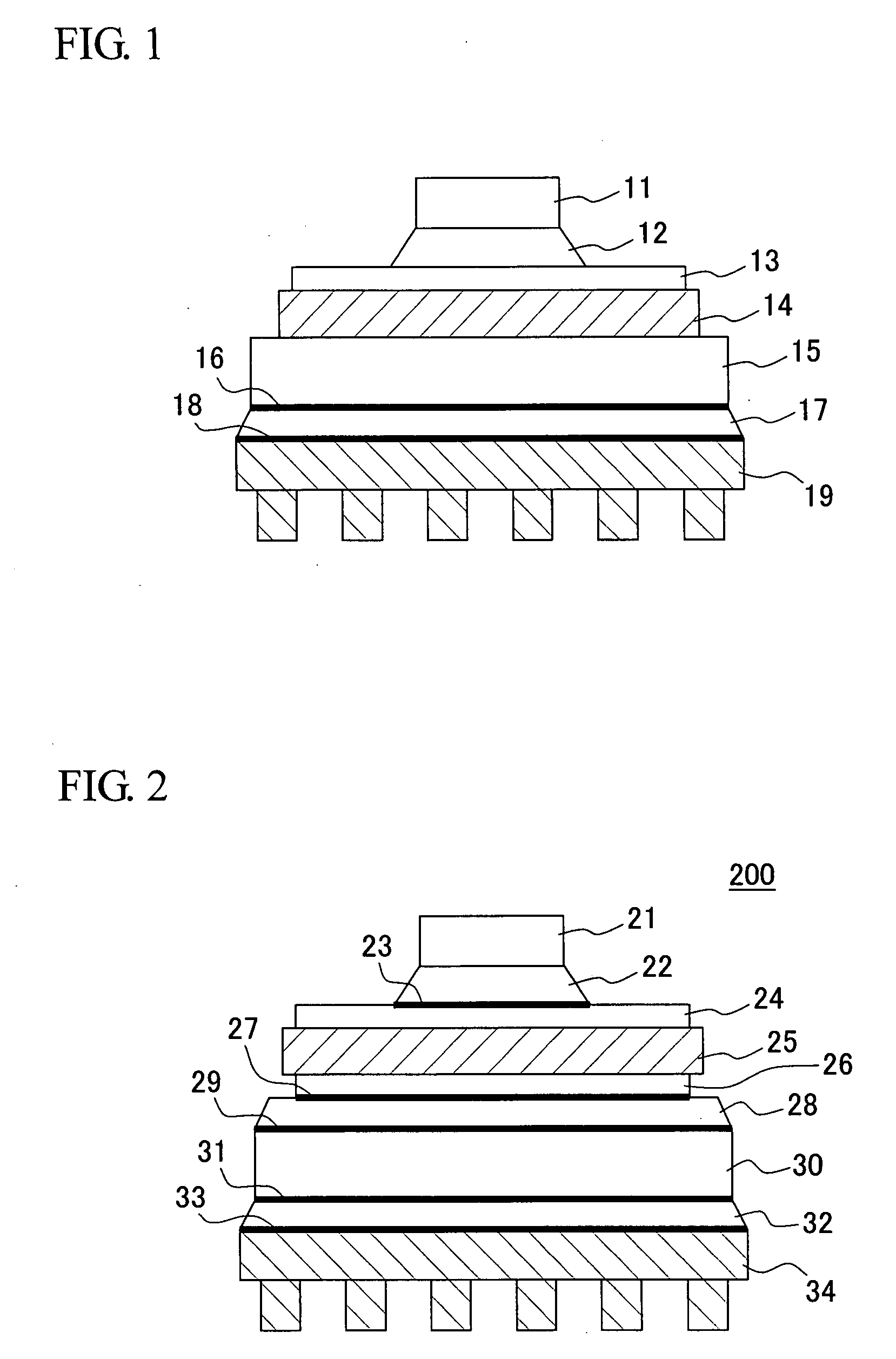
[0030]FIG. 1 shows a schematic cross section of a basic form of the power module according to the invention. A power module 100 is a 9-stage power module comprised of, from top to bottom: a power device 11 such as an IGBT chip; a metal wiring board 13 disposed on the lower surface of the power device 11 via a first solder layer 12; a metal heat dissipating plate 15 disposed on the lower surface of the metal wiring board 13 via a resin-based insulating layer 14 of thermoplastic polyimide or the like; an Ni plated layer 16 formed on the lower surface of the metal heat dissipating plate 15; a solder layer or a silicone grease layer 17; an Ni plated layer 18; and a heat sink 19, on which the Ni plated layer 18 is formed.

[0031]The heat generated by the IGBT chip is conducted by the individual layers before it is dissipated via the heat sink into water or to the air.

[0032]It is noted that instead of the conventional metal heat dissipating plate made of Cu—Mo or the like, which is relative...

embodiment 2

[0033]FIG. 2 shows a schematic cross section of a variation of the power module according to the invention. In this embodiment, the ceramic insulating material of the conventional structure is replaced by a resin-based insulating material. Specifically, a power module 200 is comprised of, from top to bottom: a power device 21 such as an IGBT chip; a first solder layer 22 disposed on the lower surface of the power device 21; an Ni plated layer 23; a metal wiring board 24; a metal plate 26 disposed on the lower surface of the metal wiring board via a resin-based insulating layer 25; an Ni plated layer 27; a second solder layer 28; an Ni plated layer 29; a metal heat dissipating plate 30; an Ni plated layer 31; a third solder layer or a silicone grease layer 32; and a heat sink 34 disposed via an Ni plated layer 33.

[0034]As in Embodiment 1, the heat generated by the IGBT chip is conducted by the individual layers before it is dissipated via the heat sink into water or to the air.

embodiment 3

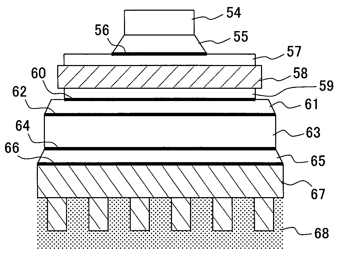
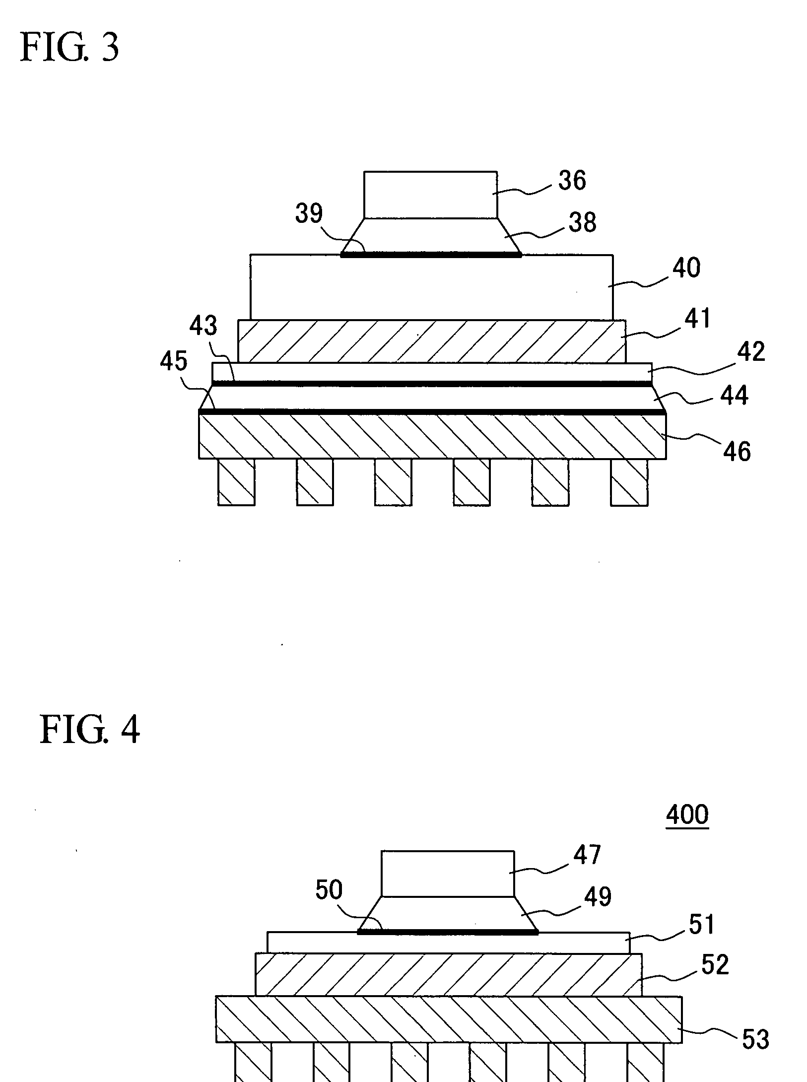
[0035]FIG. 3 shows a schematic cross section of another variation of the power module according to the invention. In this embodiment, the wiring board and the heat dissipating plate of the foregoing basic structure are combined. Specifically, a power module 300 includes, from top to bottom: a power device 36 such as an IGBT chip; a metal wiring board / metal heat dissipating plate 40 disposed on the lower surface of the power device 36 via a first solder layer 38 and an Ni plated layer 39; a metal plate 42 disposed on the lower surface of the metal wiring board / metal heat dissipating plate 40 via a resin-based insulating layer 41; an Ni plated layer 43 disposed on the lower surface of the metal plate 42; a third solder layer or a silicone grease layer 44; and a heat sink 46 disposed via an Ni plated layer 45.

[0036]As in Embodiment 1, the heat generated by the IGBT chip is conducted by the individual layers and before it is dissipated via the heat sink into water or to the air.


PUM


Abstract

The mounting structure of a power device is simplified so as to reduce cost while achieving improvements in heat dissipation and reliability. A power module 100 is comprised of a metal wiring board 13, a power device 11 disposed on an upper surface of the metal wiring board 13 via a solder layer 12, a metal heat dissipating plate 15 disposed on a lower surface of the metal wiring board 13, and a heat sink 19 disposed on a lower surface of the metal heat dissipating plate 15. A resin-based insulating layer 14 is disposed between any desired two of the aforementioned layers.

Description

BACKGROUND OF THE INVENTION[0001]1. Field of the Invention[0002]The present invention relates to a power module capable of dissipating the heat from a power device to a heat sink efficiently.[0003]2. Background Art[0004]In recent years, semiconductor integrated circuits are used in wide areas including electronic devices, and for those devices that require a particularly large amount of electric power, a power module in which a power device is mounted is used. In such a power module, in order to dissipate the large amount of heat generated by the power device as it consumes power, a multilayer heat-dissipating structure is adopted that consists of a metal wiring board on which the power device is mounted, a ceramic insulating layer of aluminum nitride or the like, a metal heat dissipating plate, and a heat sink. Thus, in the conventional heat-dissipating structure for power modules, a ceramic insulating layer of aluminum nitride or the like is used in at least one of the layers of w...

Claims


Application Information

Patent Timeline
IPC IPC(8): H01L23/36
CPCH01L23/3737H01L2224/32225H01L2924/13055H01L2924/1305H01L2924/00
Inventor ATSUMI, TAKASHIUKAI, JUNZOETO, KENJINAKAMURA, KENJIDAIZA, SEZTOMELONI, PAUL ARTHURSREERAM, ATTIGNAL N.ROBERTS, KURT DOUGLASSUTTON, DAVID LEROY
Owner TOYOTA JIDOSHA KK
Why Eureka
Try Eureka