
Tobacco vaporizer and related water pipe system

a technology of tobacco vaporizer and water pipe system, which is applied in the direction of steam generation using steam absorption, combustion air/fuel air treatment, space heating and ventilation, etc., can solve the problems of aromed vaporizer not adequately protecting the user from heat or the device from breakage, and vapor is neither cooled, nor filtered, etc., to achieve fast and smooth draw, improve airflow, and thick vapor clouds

Inactive Publication Date: 2007-12-06
WILLIAMS CLAYTON J
View PDF5 Cites 104 Cited by
  • Summary
  • Abstract
  • Description
  • Claims
  • Application Information

AI Technical Summary

Benefits of technology

[0013]It is yet another object of the present application to provide a tobacco and herb vaporizer with improved airflow and for producing thick vapor clouds. Embodiments disclosed in the present application employ passageway components and air flow apertures with sufficient diameter to allow a fast and smooth draw.
[0020]It is a further object of the present invention to provide a stylized water pipe with some hand blown components to be used in conjunction with a light activated vaporizer. An embodiment also preferably features thick colored glass, which is aesthetically pleasing to the user.

Problems solved by technology

Drawbacks of this product include, but are not limited to the absence of water filtration, so vapor is neither cooled, nor filtered of dust and metal oxides from a heating element.
This is a vaporizing product, but does not employ any significant form of water filtration technology.
However, while the AroMed product has some use for herbal therapy, it performs in a different manner, and suffers from structural limitations that effect performance.
The Aromed vaporizer does not adequately protect the user from heat or the device from breakage.
Further, airflow in this product is restricted because of inadequate ventilation and narrow components that require a user to use excess suction to draw vapors through the components.
The product has restricted vapor yield, is primarily stationary and must sit on a table.
Other limitations are that this device exposes the user to bright light and heat from the bulb, thus presenting both a safety and aesthetic limitation.

Method used


Image

  • Tobacco vaporizer and related water pipe system
  • Tobacco vaporizer and related water pipe system
  • Tobacco vaporizer and related water pipe system

Examples


Embodiment Construction

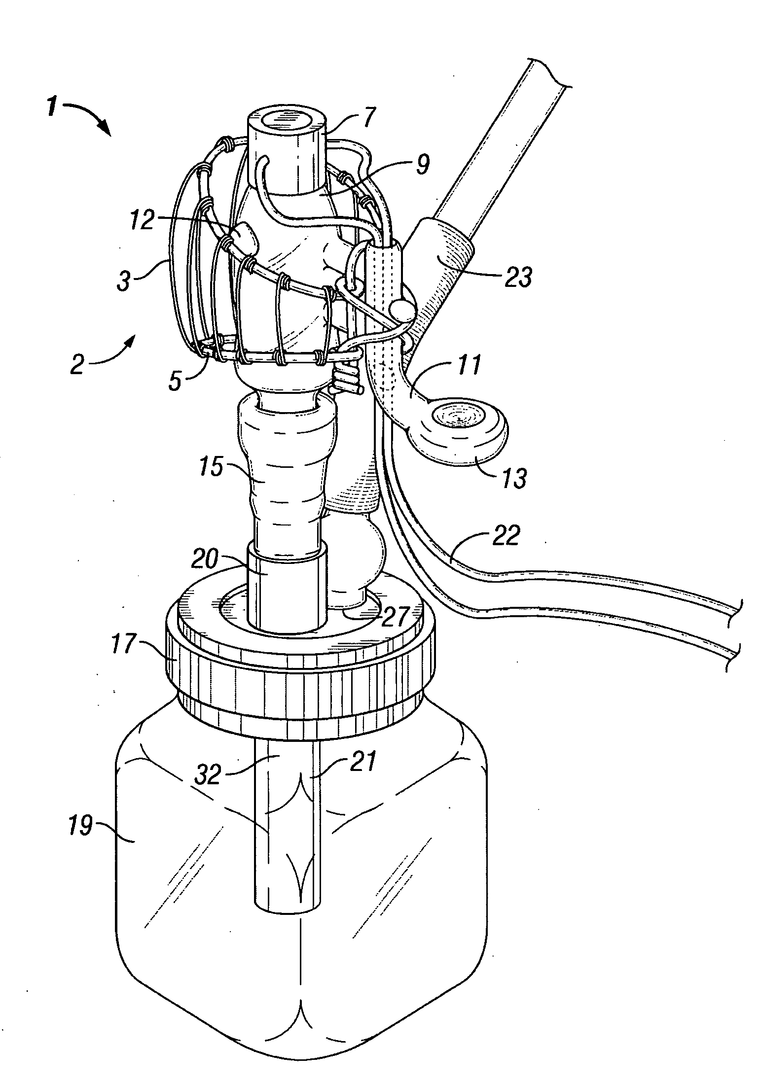
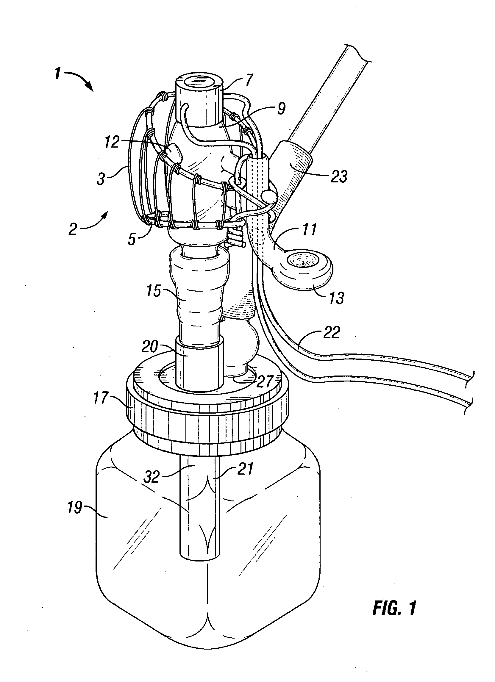
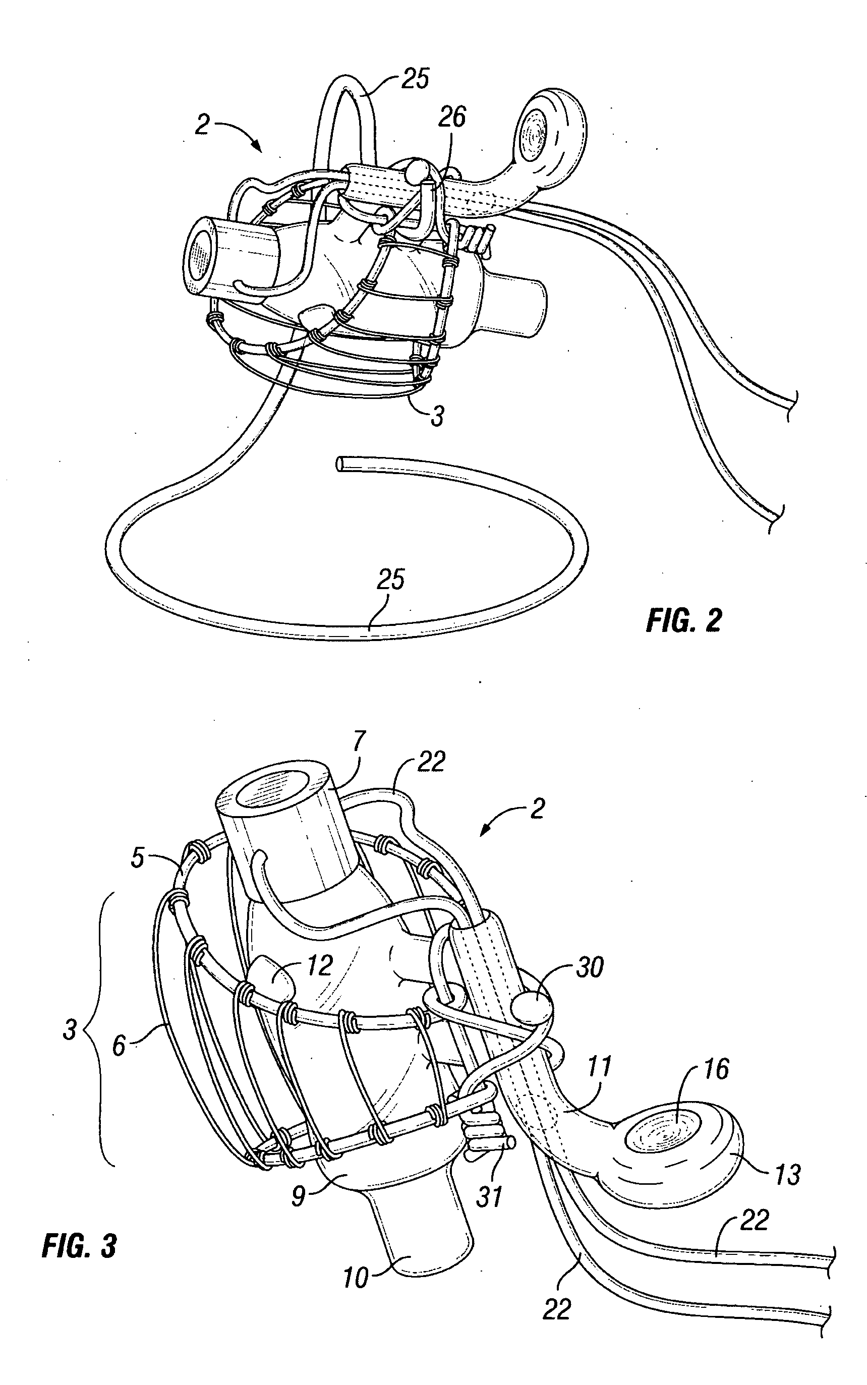
[0029]FIG. 1 is a perspective view of a preferable vaporizer pipe assembly 1. Basic components of the shown assembly comprise a vaporizer unit 2 with a heating means 7, where the vaporizer unit 2 is removably insertable into a bowl unit 15. The bowl unit 15 is a reservoir for tobacco, herbs, or other items from which vapor is extracted. The bowl unit 15 inserts into a stem 32, which stem is formed from an upper stem 20 and lower stem 21. The stem 32 extends into a chamber 19 with upper stem 20 and lower stem 21 separated by a preferable chamber top 17. The stem 32 will also be typically secured through chamber top 17 by use of a latex, rubber, cork, or synthetic rubber means, including grommets. Chamber top 17 typically features a plurality of holes formed therein, which serve to accommodate insertion by the stem 32 connected to the vapor source, chamber outlet 27, and an optional “carb” or “choke” hole. It should, however, be noted that a “carb” is not necessary with the disclosed ...


PUM

PropertyMeasurementUnit
diameteraaaaaaaaaa
diameteraaaaaaaaaa
distancesaaaaaaaaaa

Abstract

An improved vaporizer unit and water pipe assembly for extracting ingestible vapors from tobacco and herbs. Preferable embodiments of said assembly may comprise blown glass, colored glass, and adaptations for the safety of the user and to protect against breakability of said assembly. Other preferred features and embodiments include but are not limited to a cage secured to protect a central vessel housing a heating means, a hanger for storing, enhanced airflow, enhanced draw, and portability.

Description

CROSS-REFERENCE TO RELATED APPLICATIONS[0001]Not applicable.STATEMENT REGARDING FEDERALLY SPONSORED RESEARCH OR DEVELOPMENT[0002]Not applicable.BACKGROUND OF THE INVENTION[0003]1. Field of Invention[0004]The present application relates to the fields of water pipes and tobacco vaporizers.[0005]2. Background of the Invention[0006]The general concept of a water pipe has been in existence for centuries. Water pipes are also sometimes referred to as “Narghiles” or “hookahs,” with original popularity of the devices tracing back to Turkey around the time of Murat the IV around 1623-40, where they became an important part of coffee shop culture and a preferable means of smoking tobacco. (http: / / www.thehookah.com / history / 1.htm). Typical hookah tobaccos would include a mixture of shredded tobacco leaf mixed in with a sweetener such as honey, molasses or semi-dried fruit, although more modern tobaccos feature glycerin as a primary sweetener because of humectant properties and the ability to re...

Claims


Application Information

Patent Timeline
Patent Type & Authority Applications(United States)
IPC IPC(8): A61L9/03A61H33/06
CPCA24F1/30
Inventor WILLIAMS, CLAYTON J.
Owner WILLIAMS CLAYTON J
Learn More