
Objective lens, lens drive mechanism, optical pickup apparatus, and method for assembling the same

a technology of optical pickup and drive mechanism, which is applied in the direction of mountings, optics, instruments, etc., can solve problems such as deterioration in signal quality, and achieve the effect of optimizing beaming and improving control characteristics

Inactive Publication Date: 2007-11-29
SHARP KK
View PDF3 Cites 3 Cited by
  • Summary
  • Abstract
  • Description
  • Claims
  • Application Information

AI Technical Summary

Benefits of technology

The invention provides an objective lens, a lens drive mechanism, an optical pickup apparatus, and a method for assembling the same that can make apparatuses lighter and keep the weight balance in a well-balanced state. The objective lens is mounted on a lens drive mechanism, which includes a lens holder. The invention also provides a method for fixing the objective lens to the lens holder through an adhesive to keep the weight balance in a well-balanced state. The technical effects of the invention include improved dynamic characteristics of the apparatus, stabilization of recording medium, and easy and accurate tracing of disk.

Problems solved by technology

In addition to the fact that objective lens 2 according to the conventional techniques is asymmetrical, the fact that there is a difference from device to device in the relative position of the objective lens 2 with respect to the lens holder 3 causes the following problem.
13) of the lens holder 3 after the objective lens has adhered thereto is disturbed, and thus the dynamic characteristics of the lens driving apparatus 1 are disturbed, so that the accuracy in tracing the recording disk 8 may be deteriorated, resulting in a deterioration in the quality of signals.

Method used


Image

  • Objective lens, lens drive mechanism, optical pickup apparatus, and method for assembling the same
  • Objective lens, lens drive mechanism, optical pickup apparatus, and method for assembling the same
  • Objective lens, lens drive mechanism, optical pickup apparatus, and method for assembling the same

Examples


first embodiment

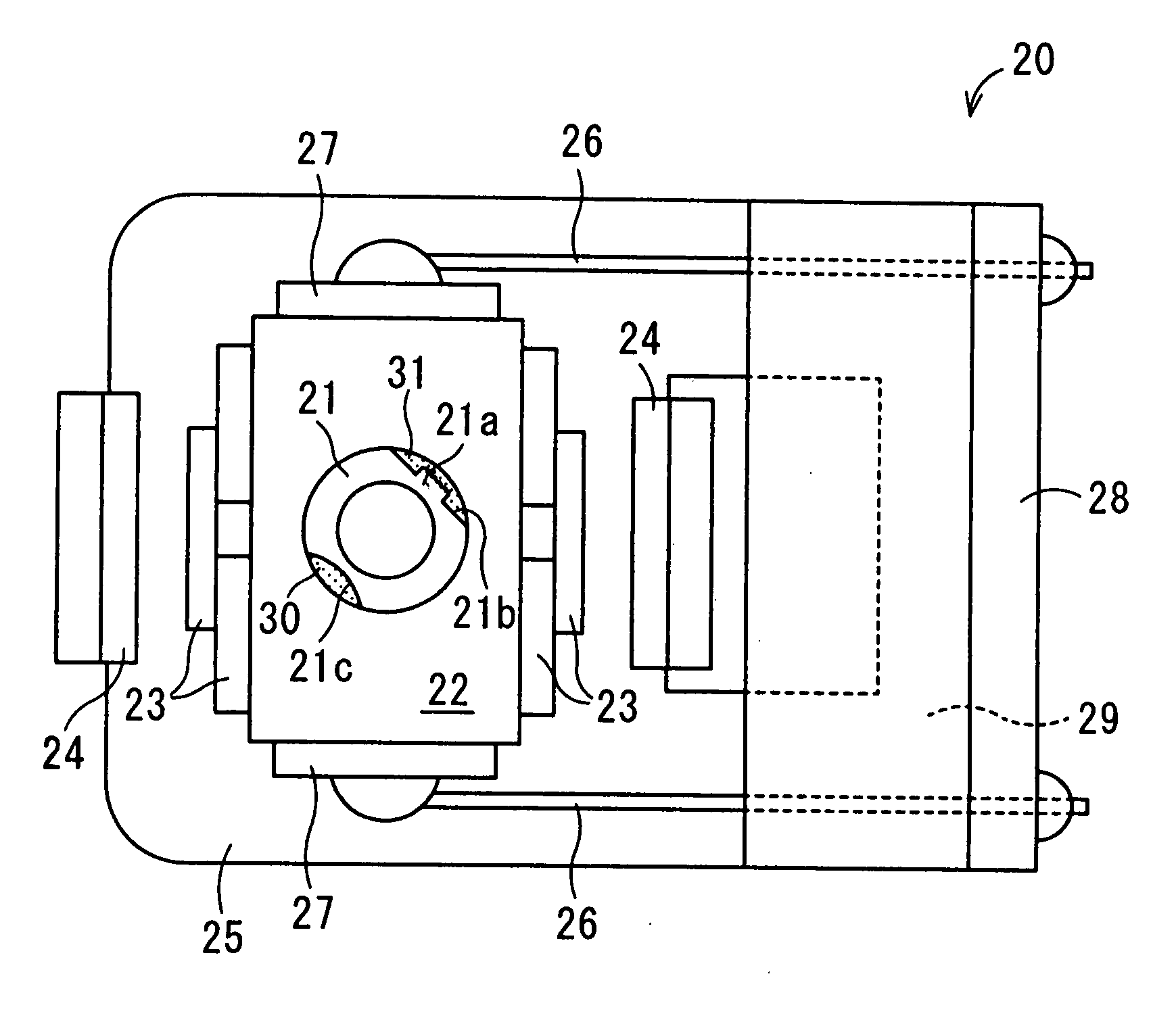
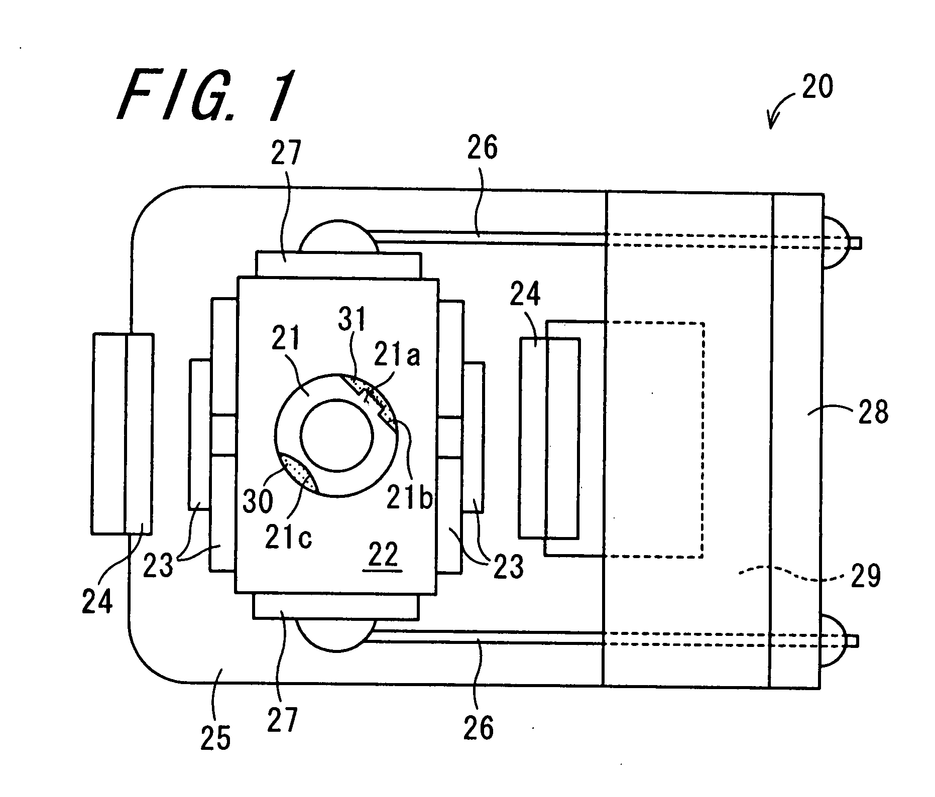
[0069]FIG. 1 is a plan view of a lens drive mechanism 20 according to the invention. An optical pickup apparatus according to this embodiment is provided with a semiconductor laser serving as a light source, abeam splitter, a collimator lens, an erecting mirror, the lens drive mechanism 20 including an objective lens 21, a beam processing lens, and a detecting element.

[0070]The lens drive mechanism 20 includes the objective lens 21, a lens holder 22, coil members 23, magnet pieces 24 and a base plate 25. The objective lens 21 narrows a laser beam from the semiconductor laser and irradiates a recording disk serving as a recording medium with the laser beam. The lens holder 22 holds the objective lens 21. The coil members 23 are fixed to the lens holder 22. The magnet pieces 24 are opposed to the coil members 23. The magnet pieces 24 are fixed to a base plate 25. Furthermore, the lens drive mechanism 20 includes a plurality of wires 26, intermediate boards 27, a main board 28 and a da...

second embodiment

[0083]The objective lens 32 according to the invention is made of a molding material using a mold so as to have a substantially circular shape when viewed from above. The circumferential portion of the objective lens 32 is provided with a gate remainder 32a that protrudes outward in the radial direction from the circumferential portion by a short distance, and that is a part of a gate left in molding. In the position that is symmetrical, with respect to the optical axis, to the gate remainder 32a on the objective lens 32, is formed a projecting portion 32b (referred to as a “balance projecting portion 32b”) for correcting the weight imbalance of the lens holder 22A, 22B, and the objective lens 32. More specifically, as shown in FIG. 4A, on the objective lens 32, in the position that is symmetrical by 180 degrees to the gate remainder 32a with respect to the optical axis, is formed the balance projecting portion 32b that protrudes outward in the radial direction from the circumferent...

third embodiment

[0094]FIG. 9 is a front view of the main portions of a partially modified example of the collimator lens in the optical pickup apparatus according to the invention. The circumferential portion of a collimator lens 33A according to this embodiment is provided with a plurality of gear-shaped projecting portions 35 at a predetermined interval in the circumferential direction. An adjusting device 37 includes a plurality of adjustment projecting portions 36 that are meshed with the gear-shaped projecting portions 35. The circumferential portion provided with the adjustment projecting portions 36 of the adjusting device 37 is configured so as to be rotatable, and can be driven to rotate at any angle using a driving source (not shown). The circumferential portion of the adjusting device 37 is driven to rotate, so that the adjustment projecting portions 36 are rotated, and the collimator lens 33A is rotated about the optical axis thereof. In this state, when it is confirmed that the quality...


PUM


Abstract

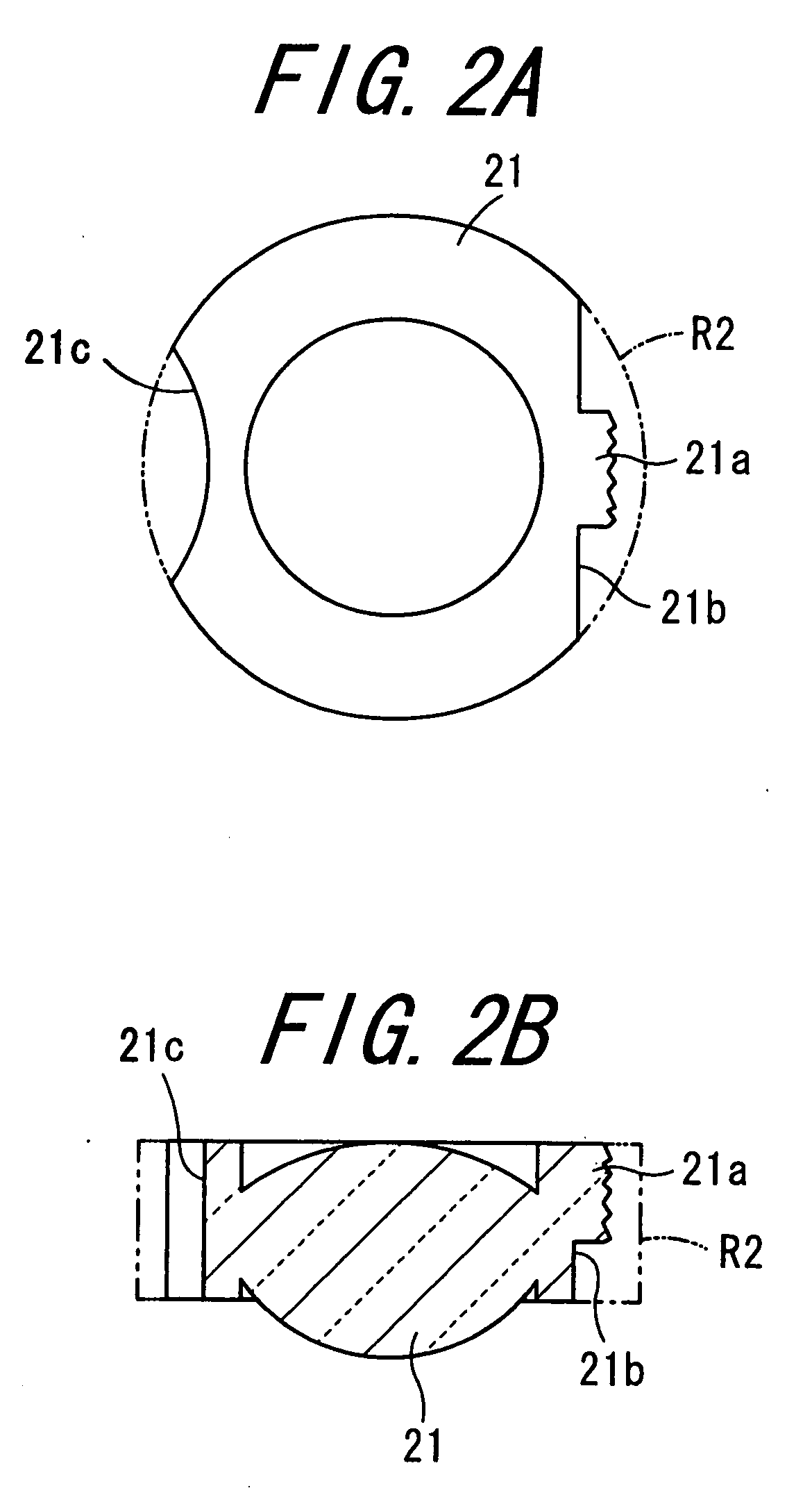
An objective lens, a lens drive mechanism, an optical pickup apparatus, and a method for assembling the same, that are capable of making the apparatuses lighter and keeping the weight balance in a well-balanced state are provided. An objective lens recess portion is formed at a position that is symmetrical, with respect to the optical axis, to a gate remainder on a objective lens. In a state where the objective lens is held on a counterbore portion of a lens holder, the objective lens is rotated about the optical axis thereof to a desired position, and then an adhesive is applied to a portion facing the gate remainder and a portion facing the objective lens recess portion, of the counterbore portion of the lens holder.

Description

CROSS-REFERENCE TO RELATED APPLICATION[0001]This application claims priority to Japanese Patent Application No. 2006-145989, which was filed on May 25, 2006, the contents of which, are incorporated herein by reference, in their entirety.BACKGROUND OF THE INVENTION[0002]1. Field of the Invention[0003]The present invention relates to an objective lens, a lens drive mechanism, an optical pickup apparatus, and a method for assembling the same.[0004]2. Description of the Related Art[0005]FIG. 12 is a cross-sectional view of a lens driving apparatus 1 according to conventional techniques. FIG. 13 is a plan view of an objective lens 2 and a lens holder 3 according to the conventional techniques. FIG. 14 is a view schematically showing an optical pickup apparatus according to the conventional techniques. As shown in FIG. 14, a predetermined amount of a laser beam radially emitted from a light source 4 is reflected by a beam splitter 5, and is changed into a substantially parallel beam when ...

Claims


Application Information

Patent Timeline
Patent Type & Authority Applications(United States)
IPC IPC(8): G02B7/02
CPCG02B7/025
Inventor KAJITA, NOBUYUKI
Owner SHARP KK
Learn More