
Precision CNC facing lathe

a technology of precision machining and facing lathe, which is applied in the field of machine tools, can solve the problems of degraded machining efficiency and workpiece machining accuracy, degraded workpiece machining accuracy or limited rotation speed of the facing head, and achieves the effects of reducing vibration of the lathe, and ensuring the smooth operation of the lath

Inactive Publication Date: 2017-04-18
YANTAI LUCHEN SEAWOO CNC MACHINERY
View PDF31 Cites 1 Cited by
  • Summary
  • Abstract
  • Description
  • Claims
  • Application Information

AI Technical Summary

Benefits of technology

The present invention provides a precision CNC facing lathe with high positioning accuracy, convenient adjustment, and improved machining efficiency. The facing head system maintains a well-balanced state during slide block adjustment, reducing vibrations and improving workpiece machining accuracy and rotational speed. The use of ball screw driving simplifies the driving system, reduces manufacturing costs, and simplifies lathe adjustment. Overall, this invention solves existing limitations in the prior art and provides a more efficient and effective facing lathe.

Problems solved by technology

However, that driving structure has some major drawbacks: first, the positioning repeatability is low and the machining efficiency and workpiece machining accuracy are degraded, due to the severe backlash between the rack and the gear during power transfer; second, the facing head system will be out of balance when the feed slide biases to a side; consequently the facing head will have vibration or shock when it rotates at a high speed, resulting in degraded work piece machining accuracy or limited rotation speed of the facing head; third, the mechanism has a complex structure and has a strict requirement for assembling accuracy.

Method used


Image

  • Precision CNC facing lathe
  • Precision CNC facing lathe
  • Precision CNC facing lathe

Examples


Embodiment Construction

[0017]Hereunder the principle and characteristics of the present invention will be detailed with reference to the accompanying drawings. However, it should be noted that the embodiments are provided only to interpret the present invention, and don't constitute any limitation to the scope of the present invention.

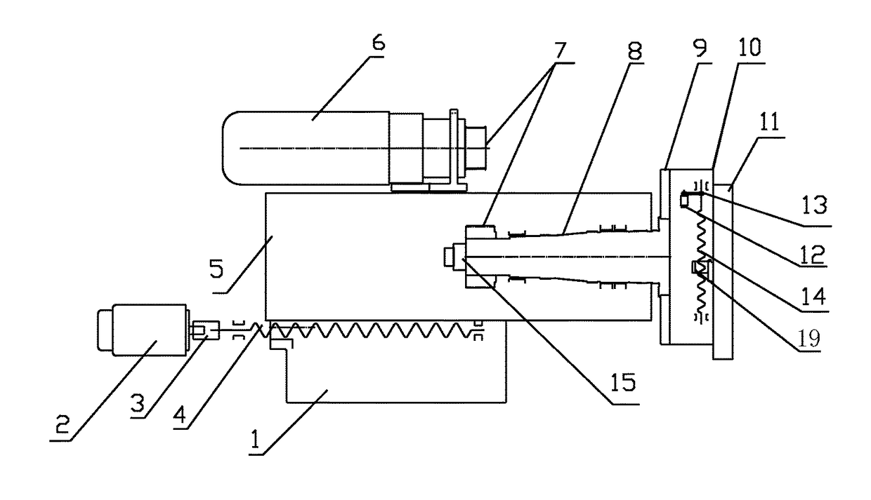
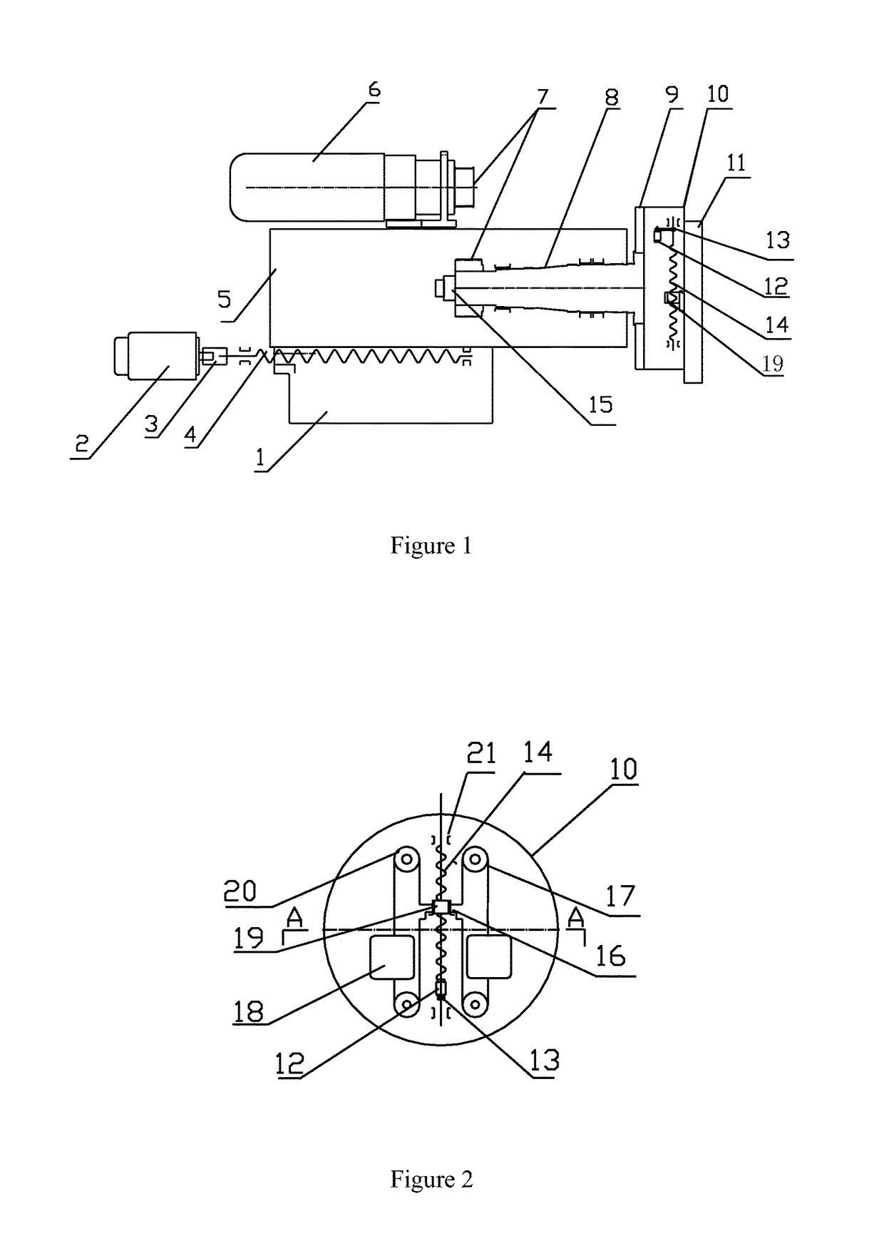
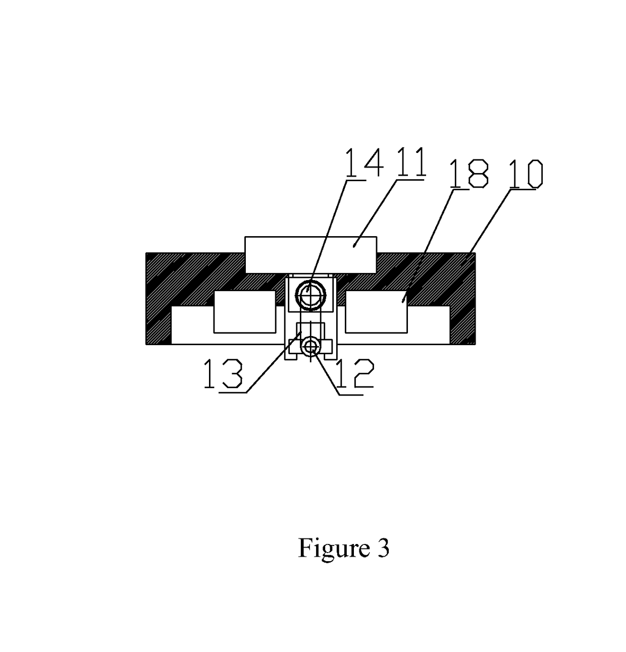
[0018]As shown in FIGS. 1˜4, the precision CNC facing lathe in an embodiment of the present invention comprises a facing head 10 that has slide ways and a feed slide 11 that is mounted in the slide ways on the facing head 10, wherein, a ball screw feeder that can drive the feed slide 11 to move in radial direction and a dynamic balancer are arranged on the facing head 10. The facing head 10 is mounted on a spindle 8 via a flange 9.

[0019]The ball screw feeder comprises a ball screw 14, an electric motor 12, a belt 13, and ball screw assembly 19, wherein, the two ends of the ball screw 14 are fixed to the facing head 10 via supporting bearings 21. The electric motor 12 is conn...


PUM


Abstract

The present invention relates to a precision CNC facing lathe, which comprises a facing head that has slide ways and a feed slide that is mounted in the slide ways on the facing head, wherein, a ball screw feeder that can drive the slide to move in radial direction and a dynamic balancer are arranged on the facing head. The dynamic balancer comprises weight blocks, a weight cable, fixed blocks, and pulleys. The lathe provided in the present invention can absolutely substitute conventional rack-and-gear driven CNC facing lathes, and can improve work piece machining accuracy and machining efficiency.

Description

FIELD OF THE INVENTION[0001]The present invention relates to the technical domain of machine tools, particularly to a precision CNC (Computerized Numerical Control) facing lathe.BACKGROUND OF THE INVENTION[0002]CNC facing lathes are widely applied in the workpiece machining field, because its radial slide can be moved conveniently on the facing head. On existing CNC facing lathes, the slide is driven by a rack-and-gear mechanism to slide in radial direction, i.e., the main rack runs across the spindle and is driven by an electric motor behind the lathe ram via the screw shaft, the other end of the main rack drives a gear in the facing head to rotate, and the gear drives a rack on the slide to move, so that the slide moves in radial direction. However, that driving structure has some major drawbacks: first, the positioning repeatability is low and the machining efficiency and workpiece machining accuracy are degraded, due to the severe backlash between the rack and the gear during po...

Claims


Application Information

Patent Timeline
Patent Type & Authority Patents(United States)
IPC IPC(8): B23Q5/44B23B29/034
CPCB23Q5/44B23B29/03439B23B29/03471B23B2250/04Y10T82/2512
Inventor TAN, SONGJIANG
Owner YANTAI LUCHEN SEAWOO CNC MACHINERY
Learn More