
Support section structure for a swing arm

a support section and swing arm technology, applied in the direction of friction roller based transmission, steering device, cycle equipment, etc., can solve the problems of increasing the weight of the entire vehicle body, unable to be avoided, and difficulty in sufficiently ensuring the distance between the pair of pivotally supporting walls, so as to achieve a well-balanced state, increase the rigidity of the vehicle body frame, and increase the weight of the vehicle body

Inactive Publication Date: 2007-08-02
HONDA MOTOR CO LTD
View PDF2 Cites 2 Cited by
  • Summary
  • Abstract
  • Description
  • Claims
  • Application Information

AI Technical Summary

Benefits of technology

[0010]Therefore, the present invention contemplates the provision of a support section structure for a swing arm which can achieve a well-balanced state with respect to the weight of the vehicle in a widthwise direction and can efficiently increase the rigidity of a vehicle body frame without inviting a significant increase in the weight of the vehicle body.
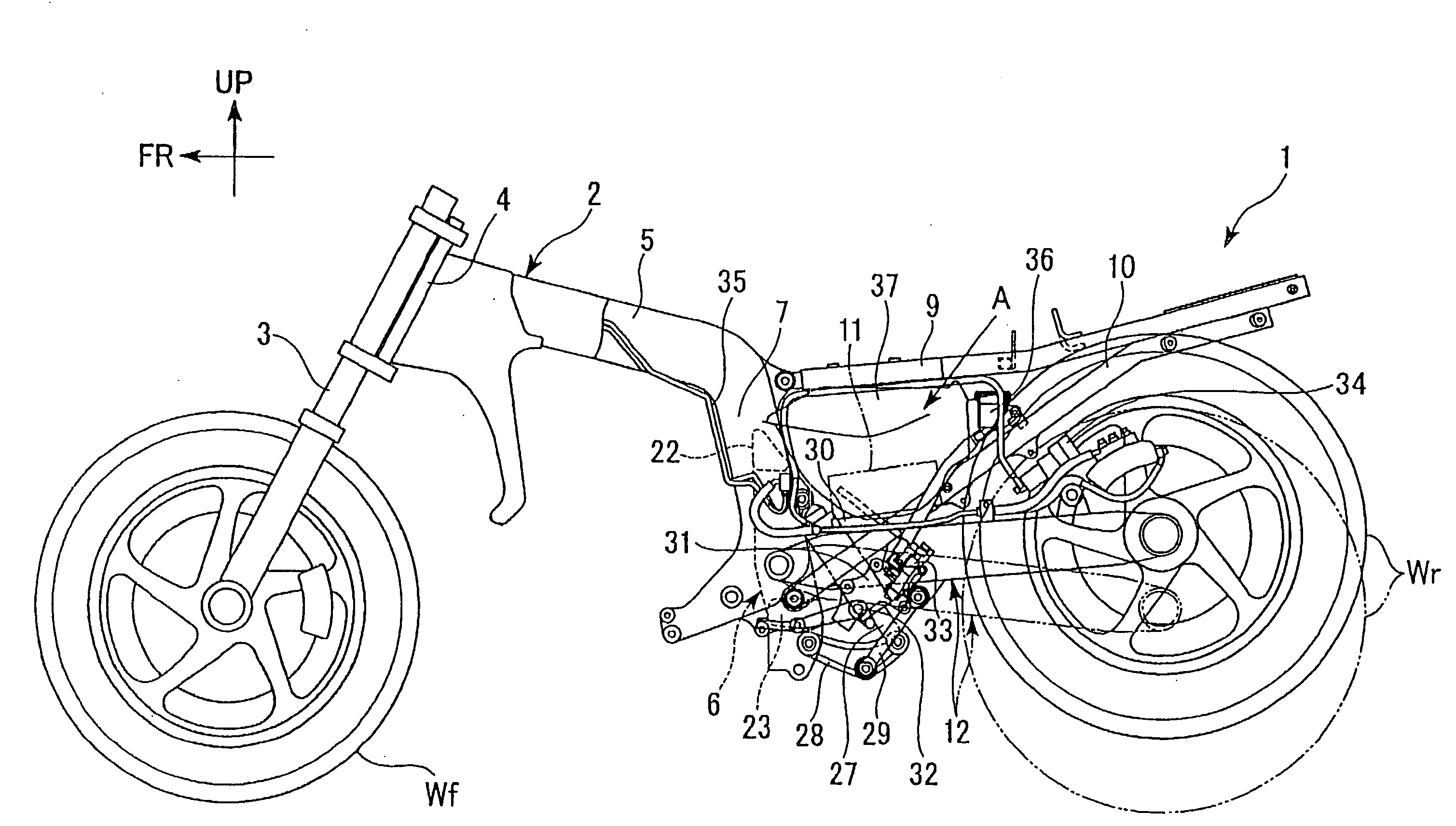
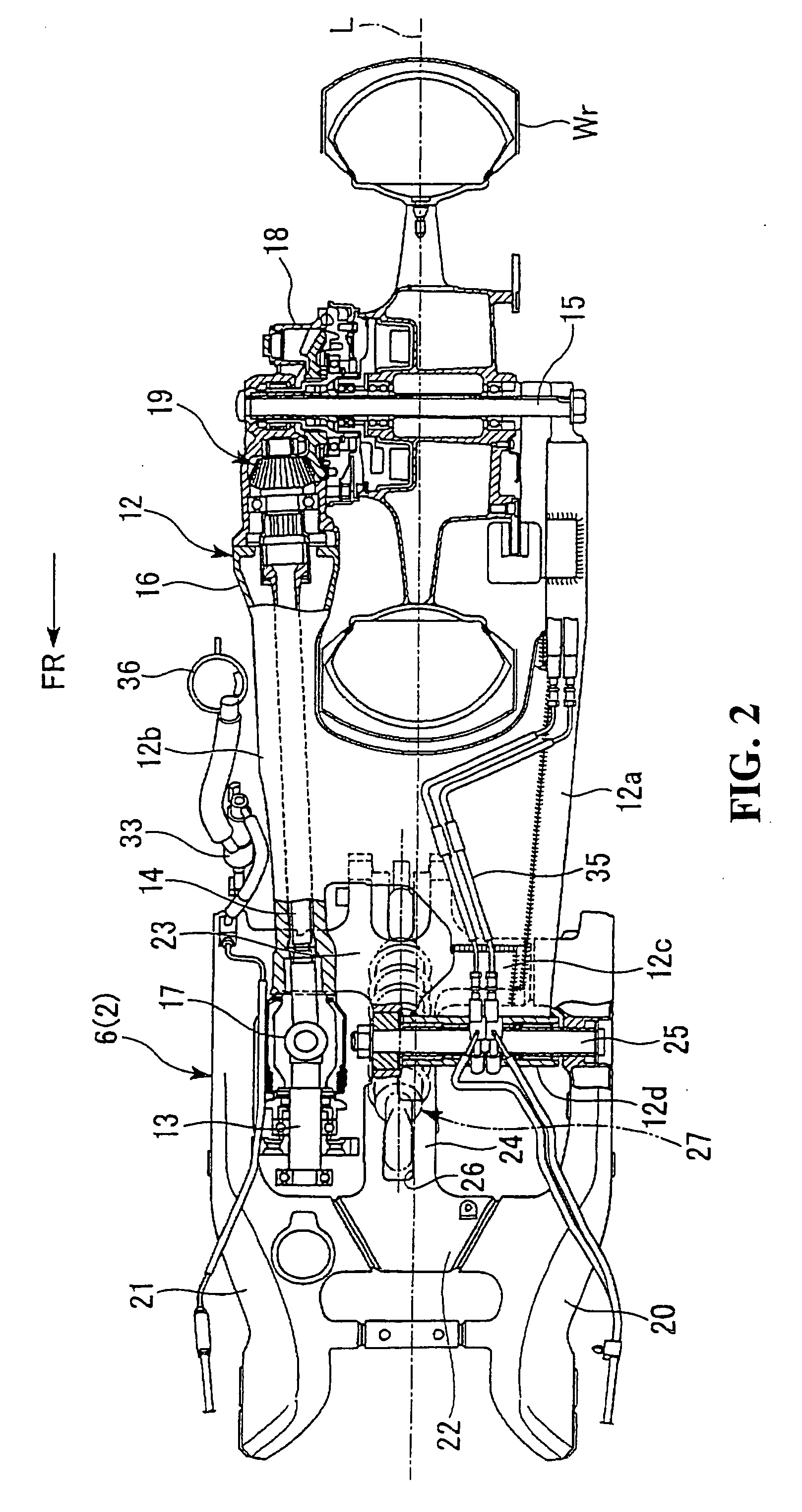
[0012]Consequently, the pair of pivotally supporting walls of the vehicle body frame are reinforced efficiently by the reinforcing wall provided integrally at the position on the outer side in the vehicle widthwise direction with respect to the drive shaft. In addition, the leftward and rightward balance in weight of the vehicle body is maintained by the reinforcing wall and the other pivotally supporting wall.
[0019]According to an embodiment of the present invention, since the pivotally supporting wall can be reinforced efficiently while the leftward and rightward balance of the vehicle body with the pivotally supporting walls is maintained by the reinforcing wall provided integrally on the vehicle body frame, an enhancement of the rigidity of the vehicle body frame can be achieved without inviting a significant increase in the weight of the vehicle body.
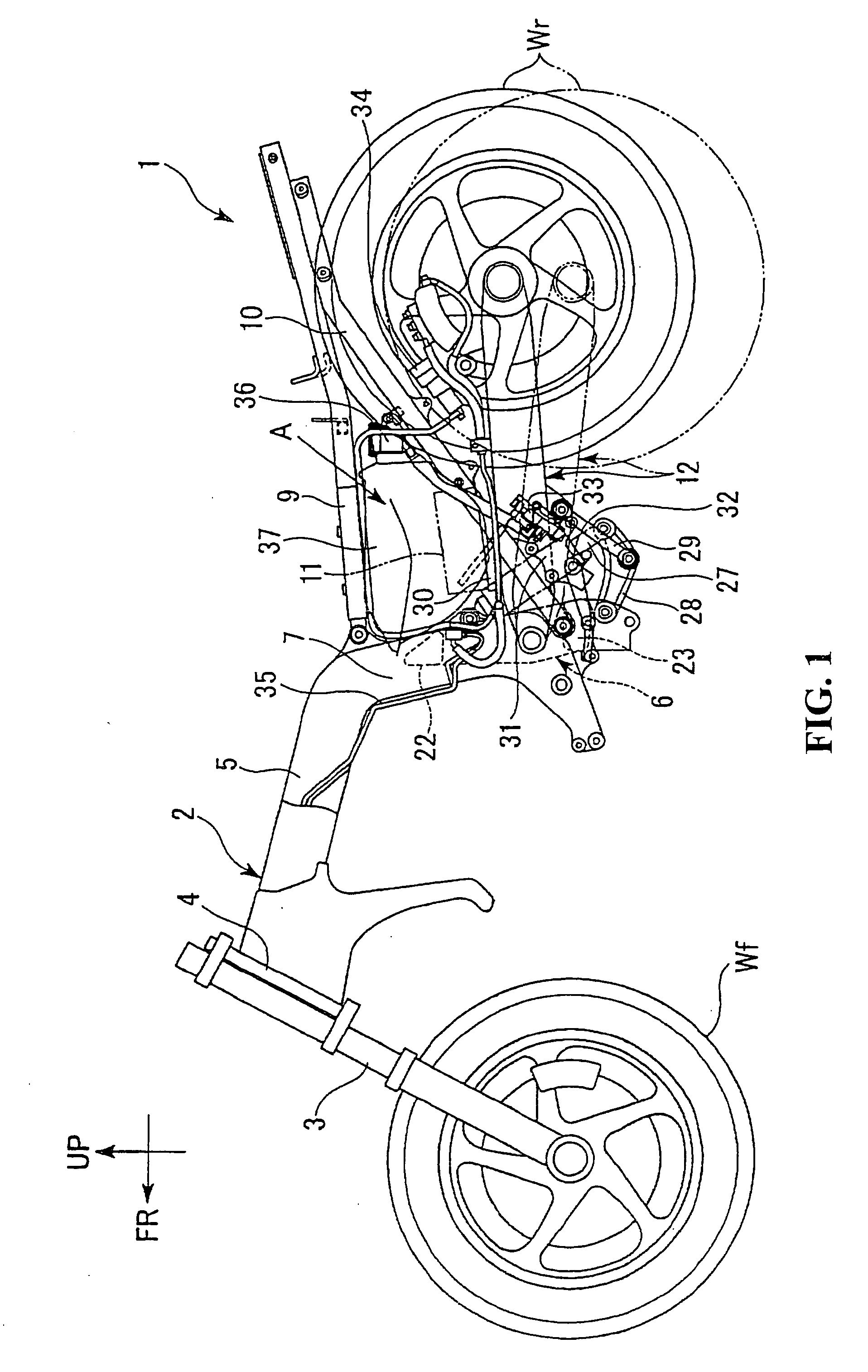
[0020]According to an embodiment of the present invention, since the rear shock absorber which is a heavy member is disposed in the proximity of the center in the vehicle widthwise direction and a load inputted from the rear shock absorber is received with certainty by that one of the pivotally supporting walls which is substantially at the center of the vehicle body frame, the vehicle balance and the motion performance of the vehicle can be efficiently raised.
[0021]According to an embodiment of the present invention, since the battery and the rear shock absorber which are heavy members are concentrated at the central position in the forward and rearward direction of the vehicle body and are distributed with a good balance to the left and right in the vehicle widthwise direction, the vehicle balance can be further improved.
[0022]According to an embodiment of the present invention, since the rear shock absorber can be disposed in an inclined relationship by a greater amount with respect to the vertical direction, the impact absorbing stroke of the rear shock absorber can be effectively assured.

Problems solved by technology

However, with the conventional support section structure for a swing arm, it is difficult to sufficiently assure the distance between the pair of pivotally supporting walls of the vehicle body frame on the opposite sides because the pivotally supporting walls are displaced to one side in the vehicle widthwise direction and the drive shaft is disposed at a side portion of one of the pivotally supporting walls.
Thus, in order to support the front end portion of the swing arm with high rigidity, it cannot be avoided to form the pivotally supporting walls in an increased size by increasing the thickness of the pivotally supporting walls or by a similar means.
As a result, there is the possibility that the weight of the entire vehicle body may be increased.
Further, in the case of the support section structure for a swing arm disclosed in Japanese Patent Laid-Open No. 2002-87364, while a cover member which covers the outer sides of the drive shaft in the vehicle widthwise direction is mounted on the vehicle body frame, this cover member is a removable cover member for the maintenance and does not contribute to an enhancement of the rigidity of the vehicle body frame.

Method used


Image

  • Support section structure for a swing arm
  • Support section structure for a swing arm
  • Support section structure for a swing arm

Examples


Embodiment Construction

[0029]In the following, an embodiment of the present invention is described with reference to the drawings. It is to be noted that, unless otherwise specified, the directions such as forward, rearward, leftward and rightward directions in the following description are the same as those of the vehicle. Further, an arrow mark FR in the figures indicates the forward direction of the vehicle, and another arrow mark UP indicates the upward direction of the vehicle.

[0030]A motorcycle 1 of the present embodiment includes a vehicle body frame 2 whose principal portion is formed from a head pipe 4 which supports a front fork 3 at a front end portion 2. A pair of side frames 5 extend rearwardly of the vehicle body in a leftwardly and rightwardly bifurcated fashion in the vehicle widthwise direction from the head pipe 4. A center frame 6 interconnects the two side frames 5 at rear end portions of the side frames 5.

[0031]Each of the side frames 5 is bent in a substantially L shape such that a r...


PUM


Abstract

A support section structure for a swing arm provides a well-balanced state for the weight of the vehicle in a widthwise direction and for efficiently increasing the rigidity of a vehicle body frame without inviting a significant increase in the weight of the vehicle body. A swing arm is provided for supporting a rear wheel Wr for rotation and is supported for a rocking motion on a center frame. An output power shaft of a power source is transmitted to the rear wheel Wr through a drive shaft. A left outer side frame and a intermediate frame, which support a front end portion of the swing arm for pivotal motion, are provided on the center frame. A right outer side frame disposed on the outer side in the vehicle widthwise direction with respect to the drive shaft on the intermediate frame is provided integrally against removal on the center frame.

Description

CROSS-REFERENCE TO RELATED APPLICATIONS[0001]The present application claims priority under 35 USC 119 to Japanese Patent Application No. 2006-023008 filed on Jan. 31, 2006 the entire contents of which are hereby incorporated by reference.BACKGROUND OF THE INVENTION[0002]1. Field of the Invention[0003]This invention relates to a support section structure for a swing arm for supporting a rear wheel of a motorcycle for a rocking motion in upward and downward directions.[0004]2. Description of Background Art[0005]Some motorcycles adopt a drive shaft as a transmission section for providing power from an engine mounted on the motorcycle.[0006]In the motorcycle which adopts the drive shaft, an output power shaft of the engine carried on a vehicle body frame and the drive shaft supported on a swing arm are connected to each other through a universal joint. Since the universal joint section is bent in response to an upward or downward rocking motion of the swing arm, the universal joint is d...

Claims


Application Information

Patent Timeline
Patent Type & Authority Applications(United States)
IPC IPC(8): B62K11/00B62M7/00B62K25/20B62M17/00
CPCB62K25/283B62K25/286
Inventor TOYODA, HIDETOSHINAKANISHI, YUTAKA
Owner HONDA MOTOR CO LTD
Learn More