
Designing an ASIC Based on Execution of a Software Program on a Processing System

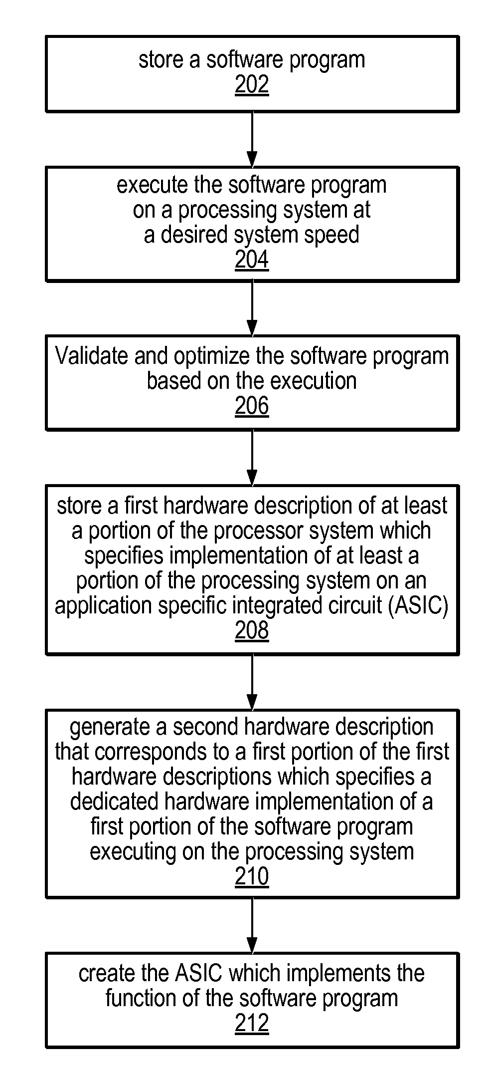
a software program and processing system technology, applied in the field of system and method for designing an asic based on a software program, can solve the problems of time-consuming and error-prone manual conversion, prove to be a complicated task, and require a difficult step to partition the design into software, etc., to achieve rapid scaling, rapid turnaround prototyping, and minimal effort

Active Publication Date: 2007-11-22
COHERENT LOGIX
View PDF12 Cites 15 Cited by
  • Summary
  • Abstract
  • Description
  • Claims
  • Application Information

AI Technical Summary

Benefits of technology

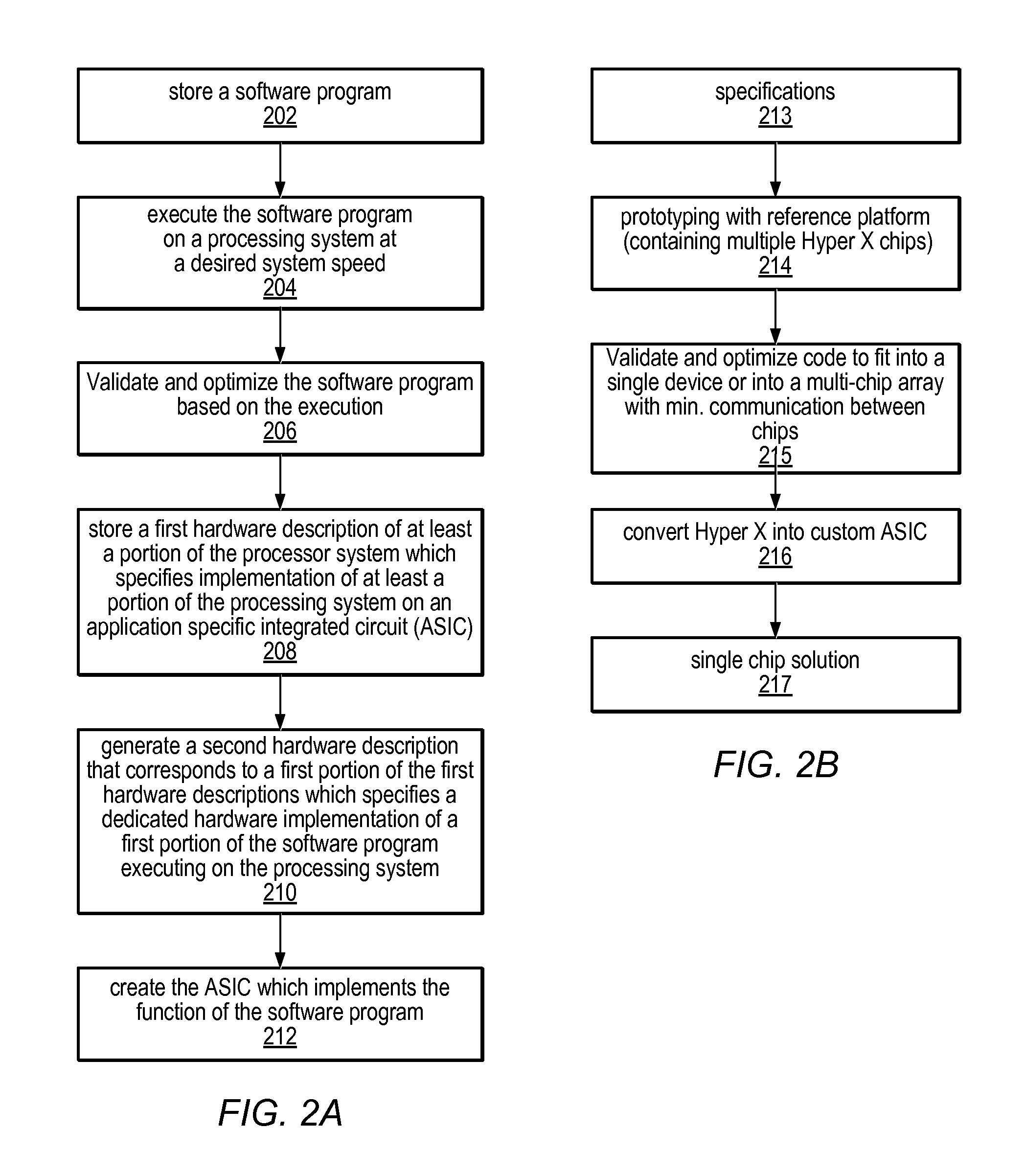
[0009]Note further that the software program may be executed on the processing system at a desired system speed. For example, the software program may execute at the desired speed of the ASIC being created. Said another way, the processing system may include sufficient hardware resources to execute the software program at a throughput level equivalent to the targeted system speed. Correspondingly, system development and debugging may be performed at full system speed without compromise. Thus, the processing system may execute in real time at the desired system speed, thereby allowing the designer to fully test the software program without assumptions regarding future performance of the ASIC.
[0010]Additionally, where further processing power is required (e.g., to achieve the desired system throughput level), further processors, memories, and / or communication paths may be added to the processing system with minimal effort. The ability to rapidly scale the processing system to meet system requirements may provide rapid turnaround prototyping capability to system design. In preferred embodiments, the redistribution of the software program over the processing system may be performed automatically and transparently to the user.
[0016]Hardening particular portions of the ASIC may allow for greater performance, smaller area, and lower power consumption. Note that one or more portions of the processing system may not be hardened, thereby allowing for programmability on the final product (in this case the ASIC). Thus, the second hardware description may be generated for the final ASIC which may be fully or partially hardened, as desired. Thus, by controlling the amount of hardening, the characteristics of the resulting ASIC may range between a programmable ASIC to a custom hardwired ASIC, achieving varying degrees of improved area, performance, and power consumption. Note that the portions to be hardened may be selected by a user, e.g., using a graphical user interface (GUI) executing on the computer system.
[0019]Additionally, the size and organization of the data memory may be optimized to fit the exact requirements of the function defined by the software. For example, unnecessary memory descriptions for unused memory may be removed from the first hardware description (to generate the second hardware description) during the hardening process. Alternatively, or additionally, memory size may be increased, memory organization may be altered or RAM descriptions may be replaced with read only memory (ROM) descriptions, e.g., to allow for greater performance and smaller area of the final ASIC.

Problems solved by technology

In many cases, this proves to be a complicated task as most high level programs do not contain clocking information which is required for the gate level logic implementation of configuring programmable hardware devices or ASICs.
Systems implemented with a mix of processors and hardwired logic also require a difficult step to partition the design into software (high level language programs executed by processors) and hardware (HDL description of gate level logic).
As a result, manual conversion is time consuming and error prone.
Automatic conversion (behavioral synthesis) often creates inefficient logic.
Hardware prototypes based on off-the-shelf, commercially available programmable devices such as FPGAs and processors often operate below the desirable system speed, which may result in additional challenges for development and verification.
In some cases, the code generated for configuring the programmable hardware element may deviate significantly from the code required for the final ASIC due to performance and resource constraints of the programmable hardware devices.
Furthermore, there is no fool-proof analytical technique to verify the correctness (functional equivalence) of the various design transformations.

Method used


Image

  • Designing an ASIC Based on Execution of a Software Program on a Processing System
  • Designing an ASIC Based on Execution of a Software Program on a Processing System
  • Designing an ASIC Based on Execution of a Software Program on a Processing System

Examples


Embodiment Construction

Incorporation by Reference:

[0031]The following references are hereby incorporated by reference in their entirety as though fully and completely set forth herein:

[0032]U.S. patent application Ser. No. 10 / 602,292, filed Jun. 24, 2003, titled “Processing system with interspersed processors and communication elements” whose inventors are Michael B. Doerr, William H. Hallidy, David A. Gibson and Craig M. Chase; and

[0033]U.S. patent application Ser. No. 11 / 691,889, filed Mar. 27, 2007, titled “Programming a Multi-Processor System”, whose inventors are John Mark Beardslee, Michael B. Doerr and Tommy K. Eng.

Terms

[0034]The following is a glossary of terms used in the present application:

[0035]Memory Medium—Any of various types of memory devices or storage devices. The term “memory medium” is intended to include an installation medium, e.g., a CD-ROM, floppy disks 104, or tape device; a computer system memory or random access memory such as DRAM, DDR RAM, SRAM, EDO RAM, Rambus RAM, etc.; or a...


PUM


Abstract

System and method for developing an ASIC. A software program may be stored which includes program instructions which implement a function. The software program may be executed on a processing system at a desired system speed and may be validated based on the execution. A first hardware description of at least a portion of the processing system may be stored and may specify implementation of at least a portion of the processing system. A second hardware description may be generated that corresponds to a first portion of the first hardware description. The second hardware description may specify a dedicated hardware implementation of a first portion of the software program executing on the processing system. Generation of the second hardware description may be performed one or more times to fully specify the ASIC. An ASIC may be created which implements the function of the software program.

Description

PRIORITY CLAIM[0001]This application claims benefit of provisional application Ser. No. 60 / 802,629 titled “Electronic System Design Method from Prototype to Application Specific Integrated Circuit” filed on May 22, 2006.FIELD OF THE INVENTION[0002]The present invention relates to the field of application specific integrated circuit (ASIC) development, and more particularly to a system and method for designing an ASIC based on a software program.DESCRIPTION OF THE RELATED ART[0003]The recent trend to use a high level programming language, such as “C”, to describe an electronic system for the purpose of improving functional verification efficiency has created a wider implementation gap between a high level model and low level hardware realization. Typically, in order to prototype the electronic device, the high level language programs are converted into a Hardware Description Language (HDL) description such as Verilog or VHDL code either manually or automatically, synthesized into gat...

Claims


Application Information

Patent Timeline
Patent Type & Authority Applications(United States)
IPC IPC(8): G06F17/50
CPCG06F17/5054G06F30/34
Inventor ENG, TOMMY K.
Owner COHERENT LOGIX
Learn More