Debris-free plastic collating strip for nails
a collating strip and plastic technology, applied in the field of collating fasteners, can solve the problems of plastic material, nail, shattering and separating from the nail shank, housekeeping problems, etc., and achieve the effect of reducing the impact of the connecting portion and reducing the amount of debris
- Summary
- Abstract
- Description
- Claims
- Application Information
AI Technical Summary
Benefits of technology
Problems solved by technology
Method used
Image
Examples
embodiment 210
[0071]FIGS. 5A and 5B illustrate an embodiment 210 in which the ribs 226 are formed at an angle γ and γ′ relative to an axis A210 of the strip 10 (as opposed to the ribs 26 in the embodiment of FIG. 1 which are generally parallel to the axis A10).
embodiment 310
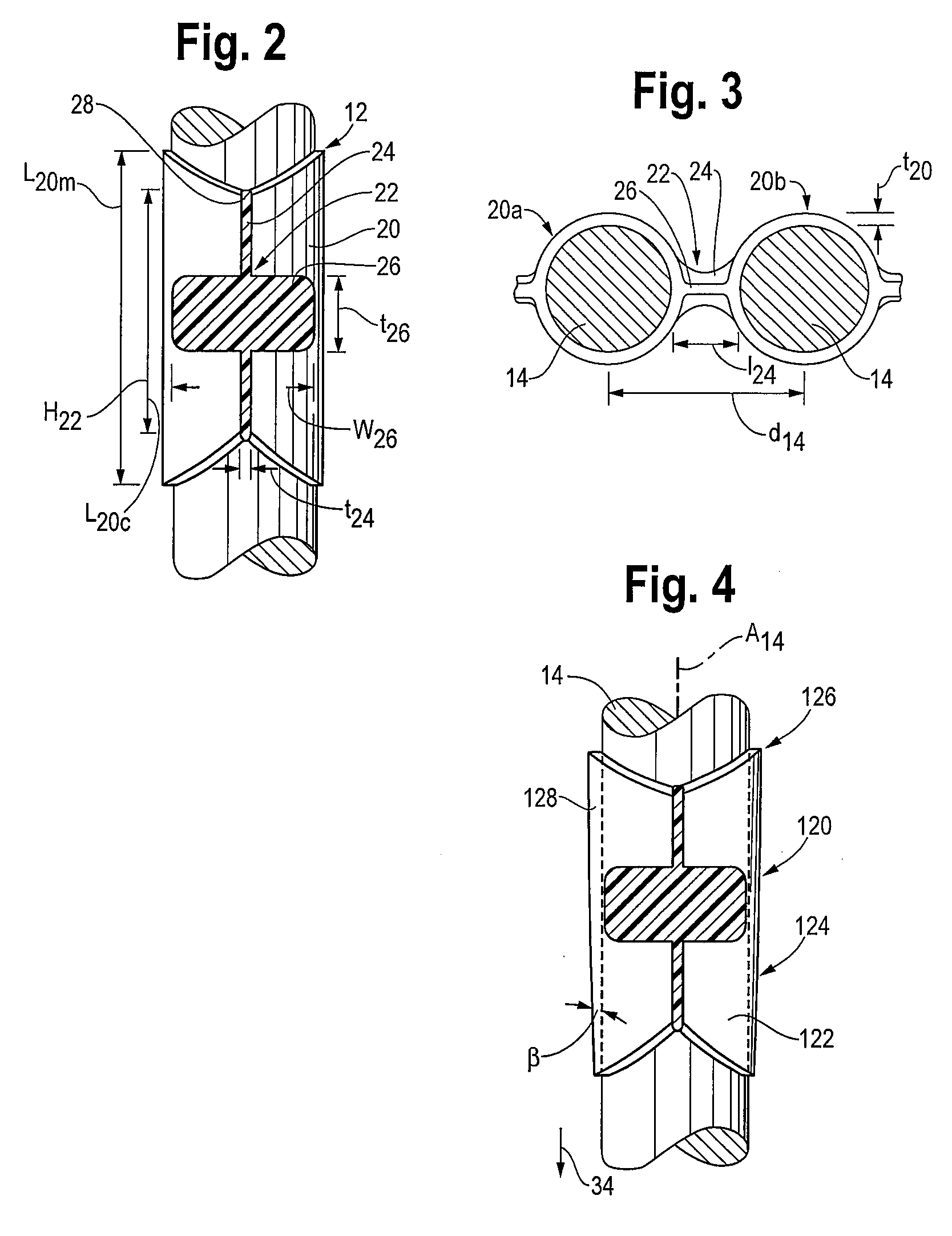
[0072]FIGS. 6 and 6A illustrate an alternate embodiment of the plastic nail collation 310 in which an embossed pattern 324 is formed in the connecting portion 322 of the strip 310, rather than the bridge 24 and rib 26 configuration (of FIGS. 1-5). In the embossed pattern 324 embodiment, a pattern of ribs 326 is formed in the connecting portion 322 that can extend in one or both directions relative to a plane P322 that is defined by the connecting 322 portion extending between the collars 320 (e.g., into or out of or both into and out of the plane P322 defined by the connecting portion 322 and the adjacent nails 14a,b). A cross-section of a one-directional embossing 324 is illustrated in FIG. 6A. The embossing 324 serves to provide a three-dimensional structure, much like the bridges 24 and ribs 26, to enhance the rigidity of the strip 310. In addition, it is anticipated that the embossing 324 can provide the necessary rigidity and predictability in separation while at the same time,...
embodiment 10
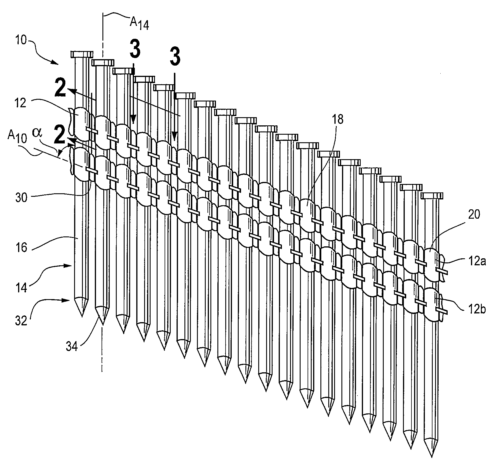
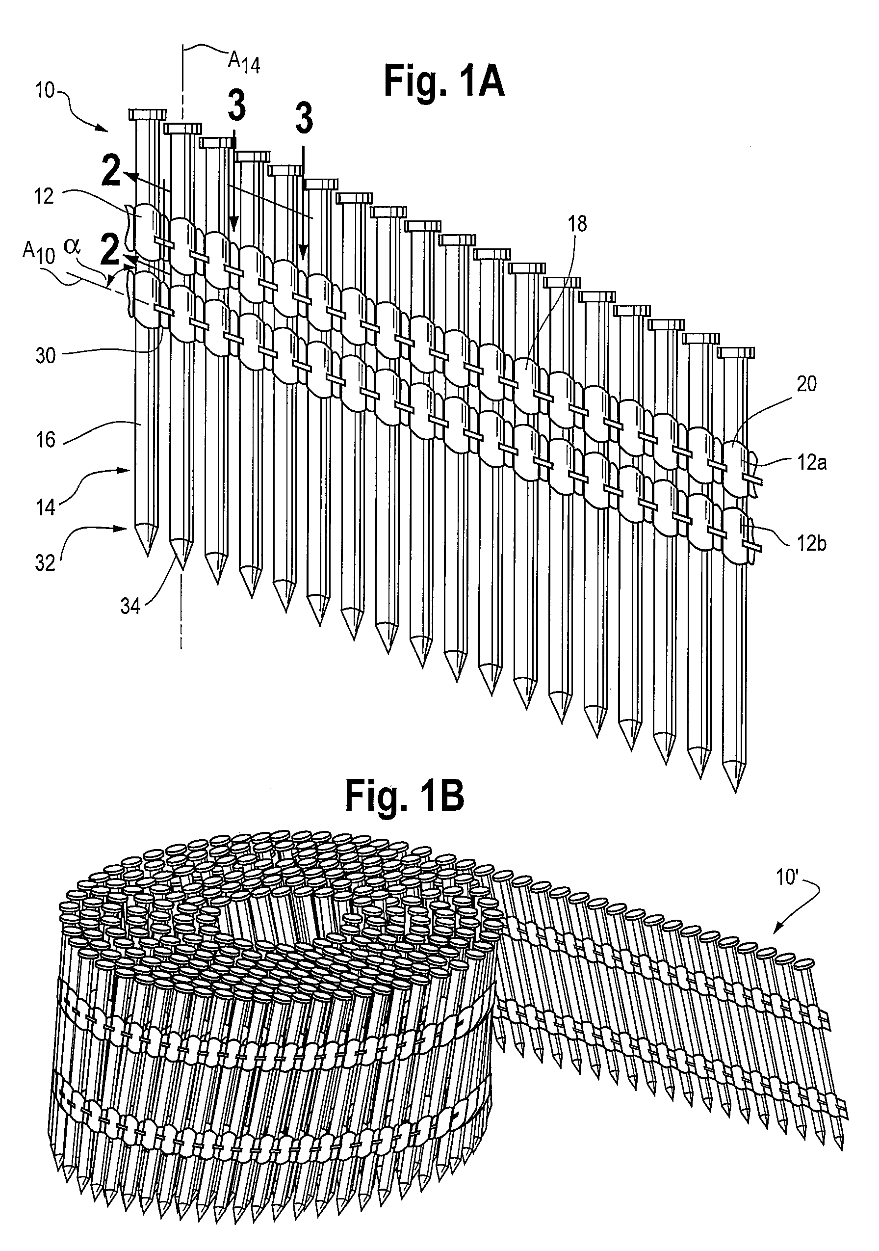
[0075]In order to provide this selectively or preferentially located separation region, a number of configurations have been examined. One such configuration is to include the notch 30 as seen in the embodiment 10 of FIG. 1 and as seen in FIGS. 8A and 8B. To effect separation of the connecting portion 22 as close to the trailing nail 14b as possible, the notch 30 should be positioned as close to the trailing nail 14b as possible.
[0076]Essentially, the strip 10 is configured with a weakened region so that separation is influenced or encouraged at a desired location. However, it should be noted that it is desirable to have the remaining portion of the connecting portion 22 remain intact as the nail 14a is driven into the substrate to reduce the debris generated. Accordingly, as seen in FIG. 8B, the notch 30 can be configured with a semi-circular notch wall 30a, and may also include a lower notch 30b to further influence separation location.
[0077]Another embodiment of the strip 410 can...
PUM
 Abstract
Description
Claims
Application Information
 - R&D
- Intellectual Property
- Life Sciences
- Materials
- Tech Scout
- Unparalleled Data Quality
- Higher Quality Content
- 60% Fewer Hallucinations
Browse by: Latest US Patents, China's latest patents, Technical Efficacy Thesaurus, Application Domain, Technology Topic, Popular Technical Reports.
© 2025 PatSnap. All rights reserved.Legal|Privacy policy|Modern Slavery Act Transparency Statement|Sitemap|About US| Contact US: help@patsnap.com


