
Engine controller

a technology of engine controller and controller, which is applied in the direction of electrical control, process and machine control, etc., can solve the problems of not correcting the difference between the exhaust air-fuel ratio and not controlling the combustion air-fuel ratio, so as to improve the exhaust emission characteristic at the cold engine start, high precision, and high stability

Active Publication Date: 2007-11-15
HITACHI ASTEMO LTD
View PDF14 Cites 12 Cited by
  • Summary
  • Abstract
  • Description
  • Claims
  • Application Information

AI Technical Summary

Benefits of technology

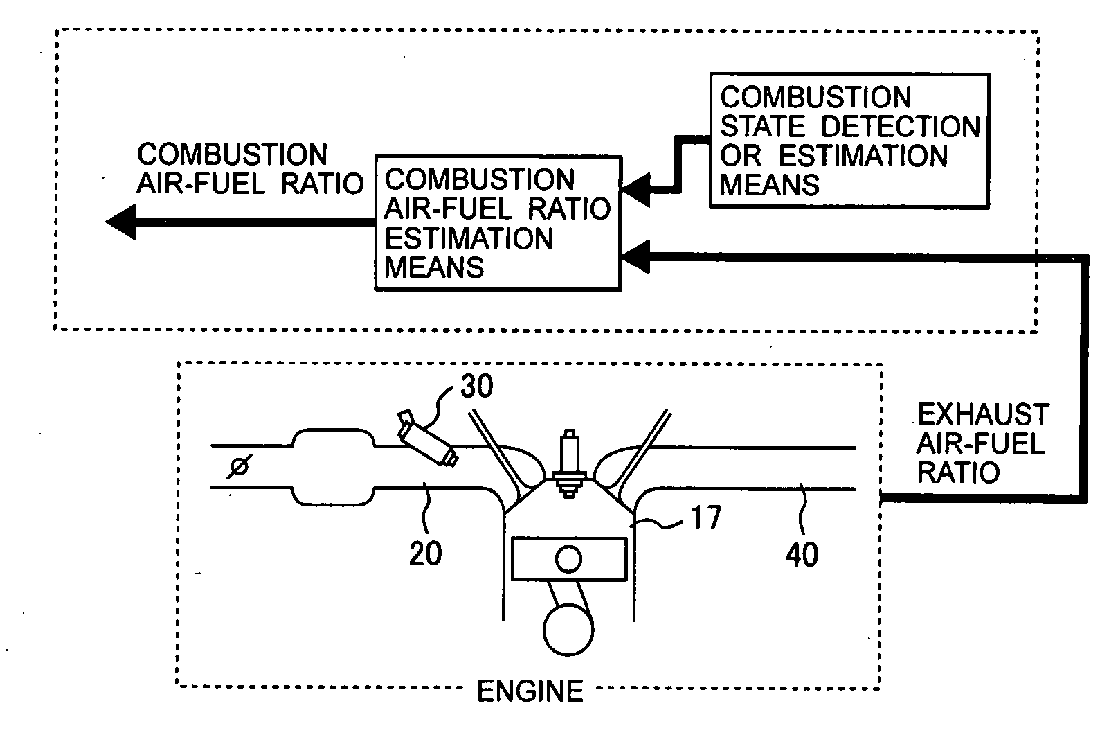
[0009]The present invention addresses the above problems with the object of providing an inexpensive engine controller that can control the combustion air-fuel ratio at the time of start with high precision.
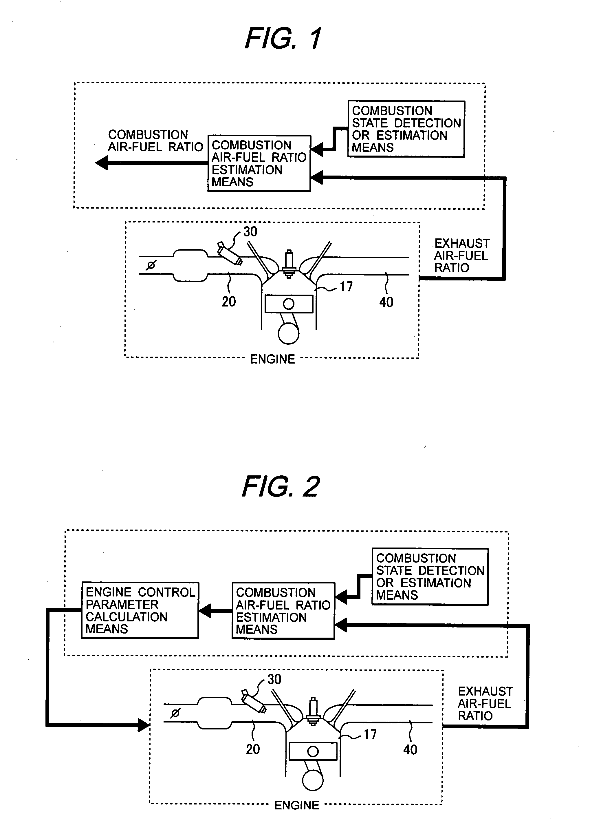
[0013]That is, since the engine is controlled according to the combustion air-fuel ratio, engine control performance is prevented from being worsened when an incorrect exhaust air-fuel ratio is detected as well as the engine control performance is improved.
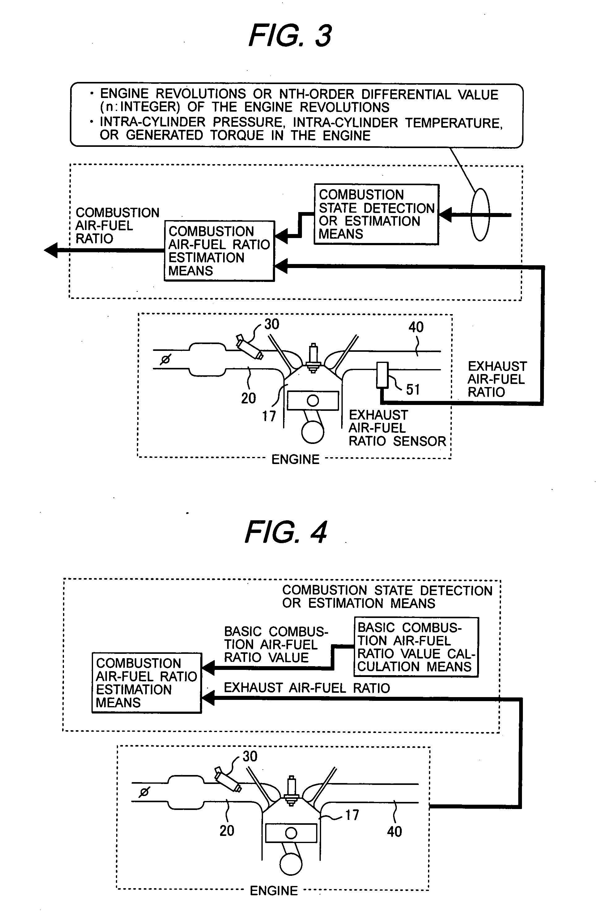
[0015]That is, the combustion state is detected or estimated according to variations in engine revolutions. In particular, when the first-order differential value, second-order differential value, and so on are used, the combustion state (variations in combustion) can be detected more precisely.
[0048]That is, in addition to the estimation or detection of the exhaust air-fuel ratio and combustion air-fuel ratio described so far, a means for calculating the supply air-fuel ratio is provided separately, making online check of the air-fuel ratio transmission system more accurate.
[0054]That is, when the equivalence ratio, which is proportional to the amount of fuel to be injected, is used to for calculation, the use of the air-fuel ratio is simplified and calculation error is lessened.
[0057]According to the present invention, the air-fuel ratio at the start of an engine can be controlled with high precision in an inexpensive manner. As a result, the exhaust emission characteristic at a cold engine start can be improved and high stability can be obtained.

Problems solved by technology

In this type of control method, however, the air-fuel ratio is just prevented from being excessively leaned; the combustion air-fuel ratio cannot be controlled to an appropriate air-fuel ratio.
In this type of control method, however, the ignition timing is just controlled by estimating a responsiveness from fuel ignition up to the control of the combustion exhaust air-fuel ratio, so the control method does not correct a difference between the exhaust air-fuel ratio and the combustion air-fuel ratio, nor does it control the combustion air-fuel ratio.
Accordingly, the control method does not addresses the problems described above.
However, there is large unevenness in the distribution of the air-fuel ratio in the cylinder, so a measurement at a single point does not yield high precision.
An air-fuel ratio sensor needs to be attached for each cylinder, resulting in a high cost.

Method used


Image

  • Engine controller
  • Engine controller
  • Engine controller

Examples


first example (

1A)

FIG. 18

[0122]FIG. 18 shows a control system indicating a controller 1A in a first example. The controller 1A comprises a basic fuel injection calculation means 120, a fuel injection correction calculation means 130, a combustion state detection means 140, and a combustion air-fuel ratio estimation means 150. The amount Ti of fuel to be injected is calculated by multiplying the basic amount Tp of fuel to be injected by Tp_hos1 obtained from calculation by the fuel injection correction calculation means 130, so that the combustion air-fuel ratios of all cylinders become desired air-fuel ratios. The value of Tp_hos1 calculated by the fuel injection correction calculation means 130 is such that the combustion air-fuel ratio becomes the desired air-fuel ratio (near the stoichiometry), particularly in an area in which the fuel vaporization rate at the time of start is low. The combustion state detection means 140 calculates a basic combustion air-fuel ratio value from a variation in ro...

second example (

1B)

FIG. 30

[0150]Although, in the first example, a variation in rotation is detected to handle it as the combustion state having a correlation to the combustion air-fuel ratio, an intra-cylinder is detected to handle it as the combustion state having a correlation to the combustion air-fuel ratio, in this example.

[0151]FIG. 30 shows a system indicating a controller 1B in this example. Basically, the controller 1B shown in the drawing is the same as in the first example, but the intra-cylinder pressure sensor 56 rather than the revolutions sensor 37 is used to detect the combustion state. That is, the detected value Pcyl (intra-cylinder pressure profile) of the intra-cylinder pressure sensor 56 instead of the revolutions sensor 37 is used to detect the combustion state (the basic combustion air-fuel ratio value is calculated). Furthermore, a supply air-fuel ratio calculation means 260 for calculating the supply air-fuel ratio is added. The description that follows focuses on means hav...

third example (

1C)

FIG. 34

[0160]Although a variation in rotation is detected to handle it as the combustion state having a correlation to the combustion air-fuel ratio in the first example and an intra-cylinder pressure is detected to handle it as the combustion state having a correlation to the combustion air-fuel ratio in the second example, an intra-cylinder temperature is detected to handle it as the combustion state having a correlation to the combustion air-fuel ratio in a third example.

[0161]FIG. 34 shows a system indicating a controller 1C in the third example. Basically, the controller 1C shown in the drawing is the same as in the second example, but the intra-cylinder temperature sensor 57 rather than the intra-cylinder pressure sensor 56 is used to detect the combustion state. That is, the value Tcyl detected by the intra-cylinder temperature sensor 57 instead of the intra-cylinder pressure sensor 56 is used to detect the combustion state (the basic combustion air-fuel ratio value is cal...


PUM


Abstract

An engine controller comprises a combustion state detection or estimation means for detecting or estimating a combustion state in the combustion chamber, a combustion air-fuel ratio estimation means for estimating a combustion air-fuel ratio in the combustion chamber according to an exhaust air-fuel ratio and the detected or estimated combustion state, and a means for calculating engine control parameters according to the estimated combustion air-fuel ratio.

Description

CLAIM OF PRIORITY[0001]The present application claims priority from Japanese application serial no. 2006-132056, filed on May 11, 2006, the content of which is hereby incorporated by reference into this application.FIELD OF THE INVENTION[0002]The present invention relates to an engine controller that controls the amount of fuel to be injected (air-fuel ratio) and other factors and, more particularly, to a controller for a robust engine that can efficiently prevents air-flow ratio precision from being worsened at the time of start.BACKGROUND OF THE INVENTION[0003]In response to the recent enhanced exhaust emission control for automobiles in North America, Europe, Japan, and other countries, the improvement of engine exhaust emission characteristics is being strongly demanded. As the performance and control precision of catalysts are being improved, exhaust emission from engines is dominant when they are started. Highly precious air-fuel ratio control is also effective in improving th...

Claims


Application Information

Patent Timeline
Patent Type & Authority Applications(United States)
IPC IPC(8): F02M7/00F02D41/00G06F19/00F02D41/14F02D45/00
CPCF02D35/023F02D35/025F02D37/02F02D41/062F02D2250/18F02D41/1458F02D41/1498F02D41/2454F02D2200/1012F02D41/1454
Inventor NAKAGAWA, SHINJIKANETOSHI, KAZUHIKOKATOGI, KOZOICHIHARA, TAKANOBUOHSUGA, MINORU
Owner HITACHI ASTEMO LTD
Learn More