Shift register circuit and image display apparatus equipped with the same
a register circuit and image display technology, applied in logic circuits, digital storage, instruments, etc., can solve problems such as display defects, pixel rewriting, unnecessarily activating gate lines, etc., to reduce noise and suppress malfunctions
- Summary
- Abstract
- Description
- Claims
- Application Information
AI Technical Summary
Benefits of technology
Problems solved by technology
Method used
Image
Examples
first embodiment
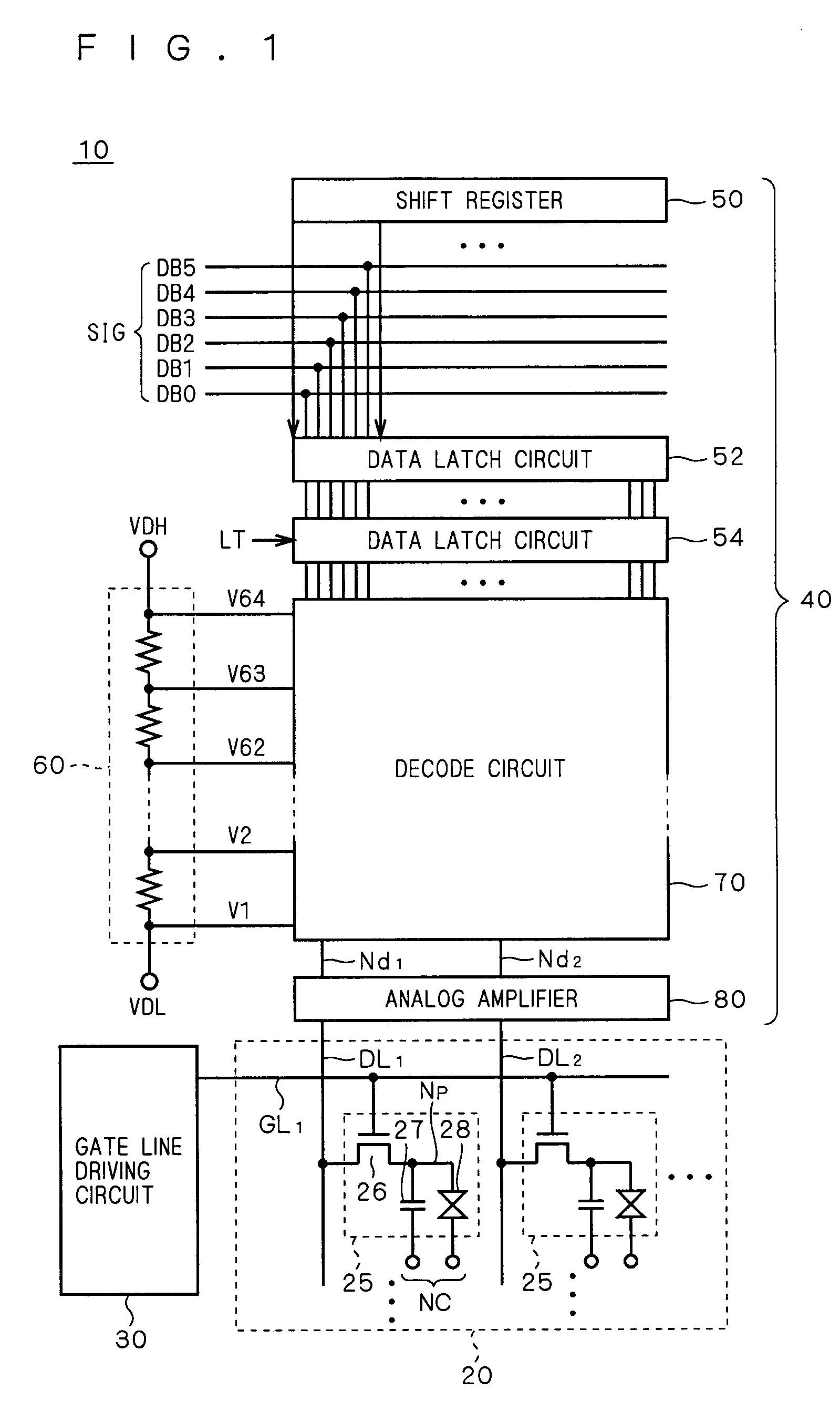
[0070]FIG. 1 is a schematic block diagram showing the configuration of a display apparatus according to a first embodiment of the present invention, showing the entire configuration of a liquid crystal display apparatus 10 as one example of the display apparatus.
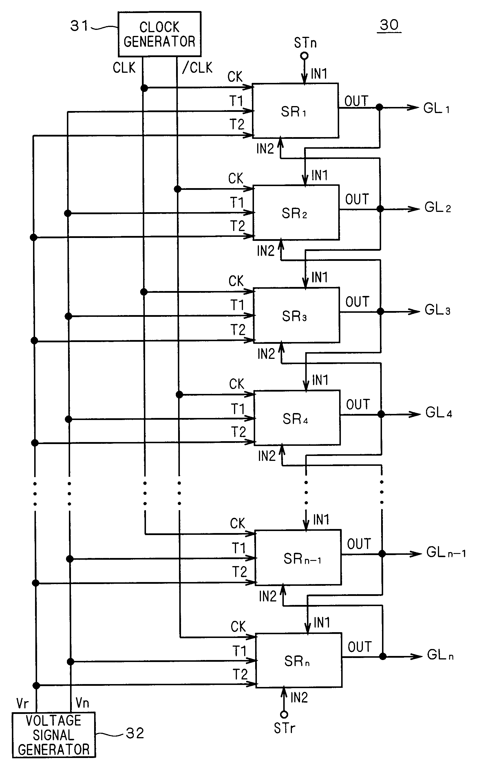
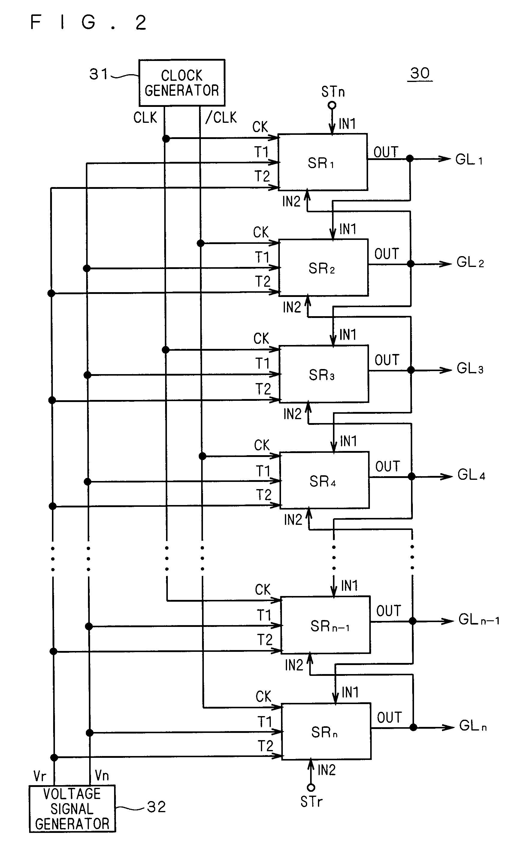
[0071]The liquid crystal display apparatus 10 includes a liquid crystal array section 20, a gate line driving circuit (scanning line driving circuit) 30, and a source driver 40. As to be apparent from the description below, the bi-directional shift register according to the embodiment of the present invention is mounted on the gate line driving circuit 30, and is integrally formed with the liquid crystal array section 20.
[0072]The liquid crystal array section 20 includes a plurality of pixels 25 arranged in a matrix form. The gate lines GL1, GL2, . . . (collectively referred to as “gate line GL”) are arranged on each row of pixels (hereinafter referred to also as “pixel line”), and the data lines DL1, DL2, . . . (collectivel...
second embodiment
[0139]FIG. 9 is a circuit diagram of a bi-directional unit shift register SR according to the second embodiment. As shown in the figure, the unit shift register SR according to the present embodiment has a configuration in which a transistor Q12 and a transistor Q13 having a relatively large driving ability are additionally arranged with respect to the conventional circuit of FIG. 3.
[0140]The transistor Q12 is connected between the node N2 and the first voltage signal terminal T1, and the gate is connected to the second input terminal IN2. That is, the transistor Q12 functions to provide the first voltage signal Vn to the node N2 (second node) based on the signal (second input signal) input to the second input terminal IN2. The transistor Q13 is connected between the node N2 and the second voltage signal terminal T2, and the gate is connected to the first input terminal IN1. That is, the transistor Q13 functions to provide the second voltage signal Vr to the node N2 based on the sig...
third embodiment
[0149]FIG. 10 is a circuit diagram showing a configuration of a bi-directional unit shift register according to the third embodiment. As shown in the figure, the unit shift register SR according to the third embodiment has a configuration in which the transistor Q12 and the transistor Q13 having a relatively large driving ability shown in the second embodiment are additionally arranged with respect to the unit shift register SR (FIG. 7) of the first embodiment.
[0150]The circuit of FIG. 7 as described in the first embodiment operates to change the node N1 from L level to H level when the output signal Gk−1 of the previous stage is input to the first input terminal IN1 (time t1 in FIG. 8) in the operation of the forward shift, for example. However, such operation is performed from a state in which the transistor Q5 is turned ON, and thus the level of the node N1 is unlikely to rise. Therefore, the rising speed of the level of the node N1 may be slow, which inhibits the operation from ...
PUM
 Abstract
Description
Claims
Application Information
 - R&D
- Intellectual Property
- Life Sciences
- Materials
- Tech Scout
- Unparalleled Data Quality
- Higher Quality Content
- 60% Fewer Hallucinations
Browse by: Latest US Patents, China's latest patents, Technical Efficacy Thesaurus, Application Domain, Technology Topic, Popular Technical Reports.
© 2025 PatSnap. All rights reserved.Legal|Privacy policy|Modern Slavery Act Transparency Statement|Sitemap|About US| Contact US: help@patsnap.com


