
System and method for adaptive control of variable valve lift tappet switching

a technology of adaptive control and variable valve lift, which is applied in the direction of electric control, combustion air/fuel-air treatment, machines/engines, etc., can solve the problems of variable delay, different valve operation, time delay, etc., and achieve the effect of reducing torque fluctuations, vibration and audible noise, and emission spikes

Active Publication Date: 2007-10-18
FORD GLOBAL TECH LLC
View PDF14 Cites 33 Cited by
  • Summary
  • Abstract
  • Description
  • Claims
  • Application Information

AI Technical Summary

Benefits of technology

[0002] Engines may use various cylinder intake and / or exhaust valve profiles to improve engine operation over a range of conditions. For example, engines may use variable valve timing, cam profile switching, and others to provide different valve operation. Switches between the different valve profiles are typically controlled via hydraulic circuits, which may have variable delays. These delays can result in valve operation different than that desired for a given combustion event.
[0007] In this way, it is possible to compensate for dynamics of the oil circuit and the delay in electronic components via combustion sensor information. Thus, it is possible to provide accurate control of a valve switching order during transition of combustion modes, thereby reducing torque fluctuations, emission spikes, vibration and audible noise. In one embodiment, information as to the timing of when each tappet has switched may be used to provide appropriate signal timing so that the correct amount of fuel can be injected into the respective cylinder, and the required temperature and pressure can be achieved inside the cylinder to perform desired combustion modes such as HCCI and SI.

Problems solved by technology

Switches between the different valve profiles are typically controlled via hydraulic circuits, which may have variable delays.
These delays can result in valve operation different than that desired for a given combustion event.
However, the inventors herein have recognized disadvantages with such an approach, especially when applied to an engine changing combustion modes during the switch in valve operation, such as between a spark ignition combustion and a compression ignition combustion.
For example, the time delay may include factors such as delays in the electronic and solenoid valves.
In addition, external conditions such as humidity or altitude may affect the response time of the tappet switch order required for transitioning combustion modes between different combustion modes, such as spark and compression ignition.
Finally, errors in tappet switching may result in undesired combustion modes in cylinders and may cause engine misfires in a compression ignition mode, for example.

Method used


Image

  • System and method for adaptive control of variable valve lift tappet switching
  • System and method for adaptive control of variable valve lift tappet switching
  • System and method for adaptive control of variable valve lift tappet switching

Examples


Embodiment Construction

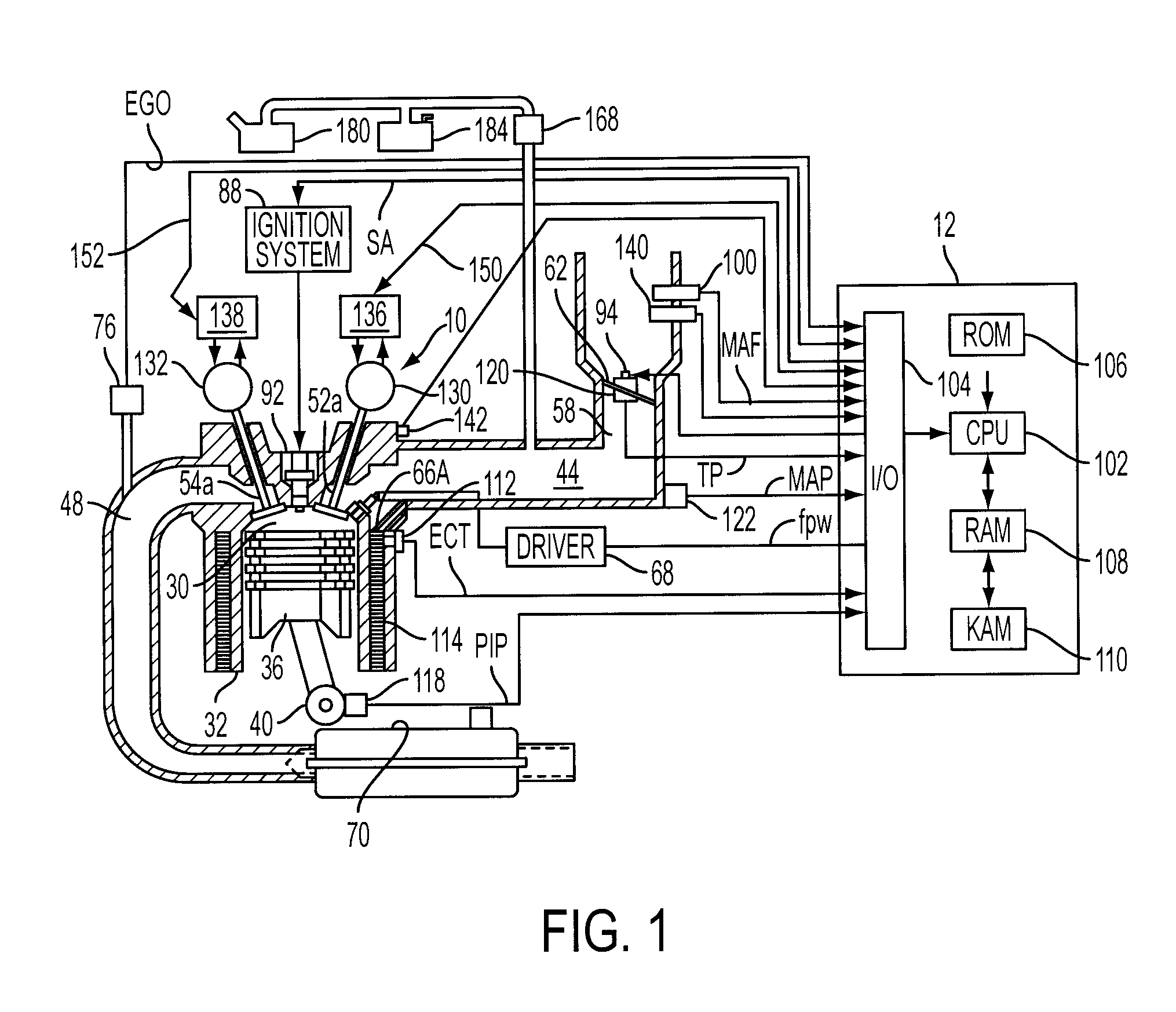
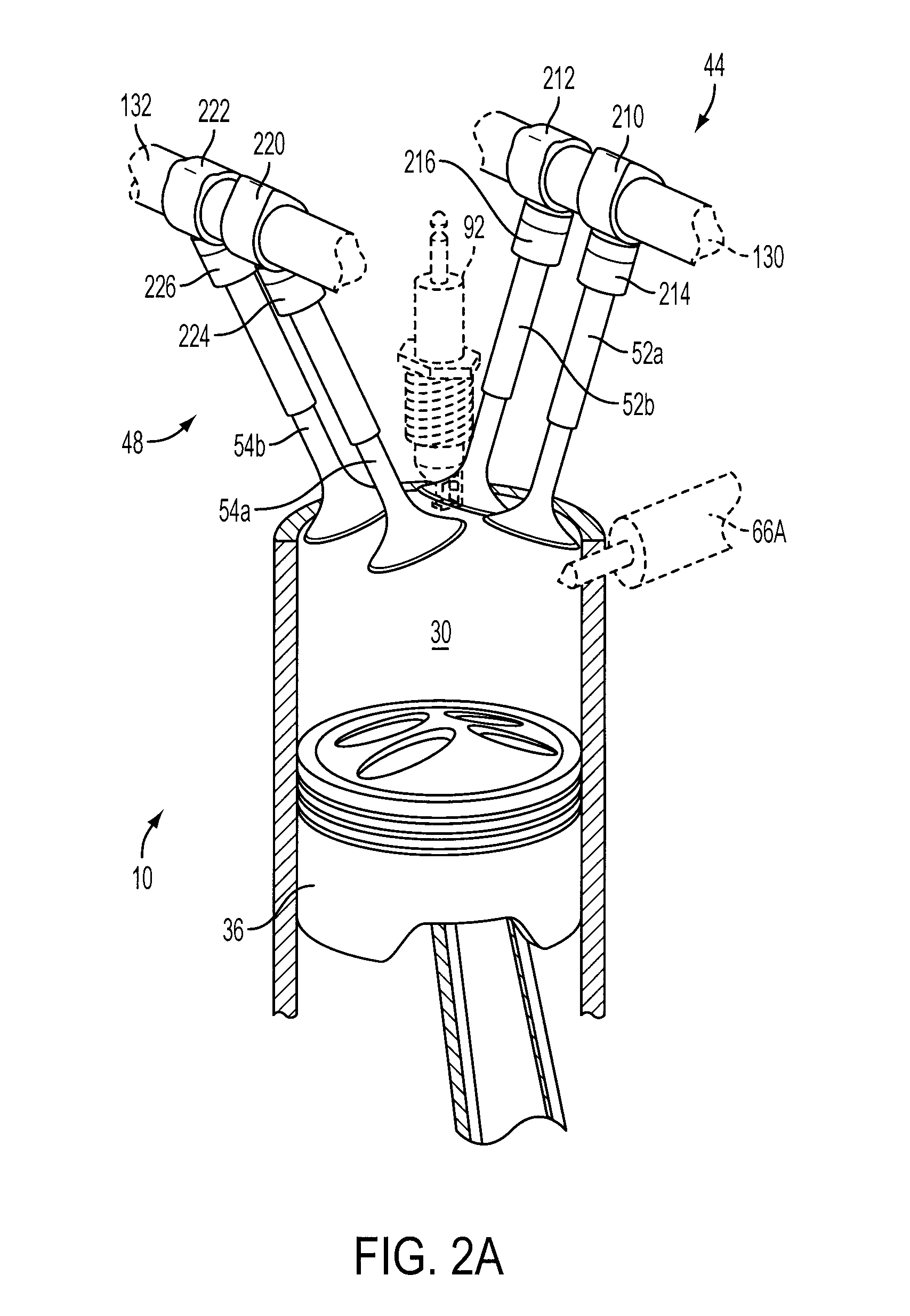
[0019]FIG. 1 shows one cylinder of a multi-cylinder engine, as well as the intake and exhaust path connected to that cylinder. Continuing with FIG. 1, direct injection internal combustion engine 10, comprising a plurality of combustion chambers, is controlled by electronic engine controller 12. Combustion chamber 30 of engine 10 is shown including combustion chamber walls 32 with piston 36 positioned therein and connected to crankshaft 40. A starter motor (not shown) is coupled to crankshaft 40 via a flywheel (not shown). Combustion chamber, or cylinder, 30 is shown communicating with intake manifold 44 and exhaust manifold 48 via respective intake valves 52a and 52b (not shown, see FIG. 2), and exhaust valves 54a and 54b (not shown, see FIG. 2). Fuel injector 66A is shown directly coupled to combustion chamber 30 for delivering injected fuel directly therein in proportion to the pulse width of signal fpw received from controller 12 via electronic driver 68. The fuel injector may be...


PUM


Abstract

A method of controlling cylinder valve switching between a first valve condition and a second valve condition for transitioning between combustion modes of an engine comprises adjusting timing of a signal to switch between said valve conditions in response to information from a combustion sensor, wherein said combustion modes include spark ignition and homogeneous compression ignition.

Description

FIELD [0001] The present application relates to systems and methods for control of variable valve lift tappet switching during transition of combustions modes. BACKGROUND AND SUMMARY [0002] Engines may use various cylinder intake and / or exhaust valve profiles to improve engine operation over a range of conditions. For example, engines may use variable valve timing, cam profile switching, and others to provide different valve operation. Switches between the different valve profiles are typically controlled via hydraulic circuits, which may have variable delays. These delays can result in valve operation different than that desired for a given combustion event. [0003] One approach considering the delay of an oil circuit for changing valve characteristics is described in U.S. Pat. No. 6,330,869 where the combustion before and after the changeover of valve operation is a spark ignited combustion. In this reference, the property of the working oil in the hydraulic valve characteristic ch...

Claims


Application Information

Patent Timeline
IPC IPC(8): F01L1/34
CPCF01L1/143Y02T10/18F01L13/0036F01L2001/0537F01L2001/34496F01L2800/00F02B1/12F02B17/005F02B23/104F02B2075/125F02D13/0211F02D13/0257F02D13/06F02D35/02F02D35/023F02D35/027F02D41/0082F02D41/2464F02D41/3035F02D41/3047F02D41/307F02D2041/001F02D2200/0418F02M25/0715F02M25/0752F02M25/089F02M31/042Y02T10/128F02D35/021F01L1/25F02M26/13F02M26/01F02D41/3041F02D41/2451Y02T10/12
Inventor PETRIDIS, THEMI PHILEMON
Owner FORD GLOBAL TECH LLC
Learn More