Vertical-type heat processing apparatus and method of controlling transfer mechanism in vertical-type heat processing apparatus

Inactive Publication Date: 2007-10-11
TOKYO ELECTRON LTD
View PDF4 Cites 22 Cited by
  • Summary
  • Abstract
  • Description
  • Claims
  • Application Information

AI Technical Summary

Benefits of technology

[0005] In order to cope with the above situation, it has been proposed to dispose on the transfer mechanism a vibration sensor for detecting an impact or vibrations generated upon collision of the abnormal wafer with the transfer mechanism. When the vibration sensor detects vibrations exceeding a predetermined intensity, the drive of the transfer mechanism is stopped, whereby the damage of the wafers and the boat can be restrained.
[0006] However, provision of such a vibration sensor on, e.g., the substrate supporter invites a complicated structure of the mechanism and increase in costs. Further, detection precision and detection speed (response) of the vibration sensor are limited, since the sensor senses the vibrations upon generation thereof by an impact, and then converts the same into electric signals. Thus, a sufficient effect for restraining the damage of the wafers and the boat has not yet been achieved.
[0007] In view of the above problems, the present invention has been made to effectively solve the same. The object of the present invention is to provide a vertical-type heat processing apparatus with a simple structure for reducing costs, which can restrain the damage of an object to be processed and a holder as much as possible due to an improved detection speed, and a method of controlling a transfer mechanism in the vertical-type heat processing apparatus.
[0009] For example, when there is an object to be processed which is disengaged from a groove in the substrate holder, and the substrate supporter approaches and interferes with the abnormal object to be processed (the substrate supporter is prevented from moving forward), the encoder value outputted from the encoder of the pitch-change driving part changes correspondingly. According to the present invention, the impact and the resultant abnormal drive of the transfer mechanism and the presence of the abnormal object to be processed in the holder can be quickly and readily detected, without the aid of a vibration sensor or the like. Namely, owing to the improved detection speed, the drive of the transfer mechanism can be stopped immediately after the judgment of the abnormal drive. Thus, the damage of the objects to be processed and the holder can be minimized. In addition, the present invention can realize a simplified structure and decrease in costs.
[0011] For example, when the controller judges that the transfer mechanism is abnormally driven, the controller is adapted to stop the drive of the transfer mechanism in such a manner that the controller immediately stops the substrate supporter or immediately moves the substrate supporter rearward and then stops the substrate supporter. In this case, the substrate holder can be prevented from turning over, and the damages of the objects to be processed and the holder can be more effectively restrained.

Problems solved by technology

However, provision of such a vibration sensor on, e.g., the substrate supporter invites a complicated structure of the mechanism and increase in costs.
Further, detection precision and detection speed (response) of the vibration sensor are limited, since the sensor senses the vibrations upon generation thereof by an impact, and then converts the same into electric signals.
Thus, a sufficient effect for restraining the damage of the wafers and the boat has not yet been achieved.

Method used


Image

  • Vertical-type heat processing apparatus and method of controlling transfer mechanism in vertical-type heat processing apparatus
  • Vertical-type heat processing apparatus and method of controlling transfer mechanism in vertical-type heat processing apparatus
  • Vertical-type heat processing apparatus and method of controlling transfer mechanism in vertical-type heat processing apparatus

Examples


Embodiment Construction

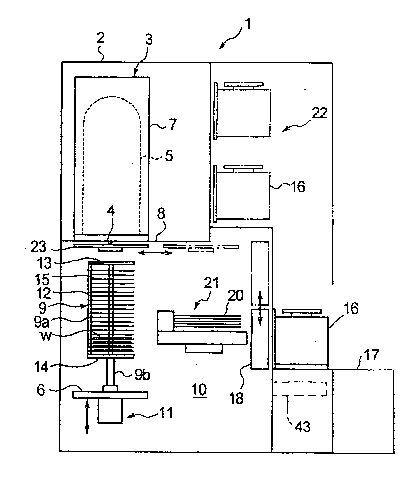
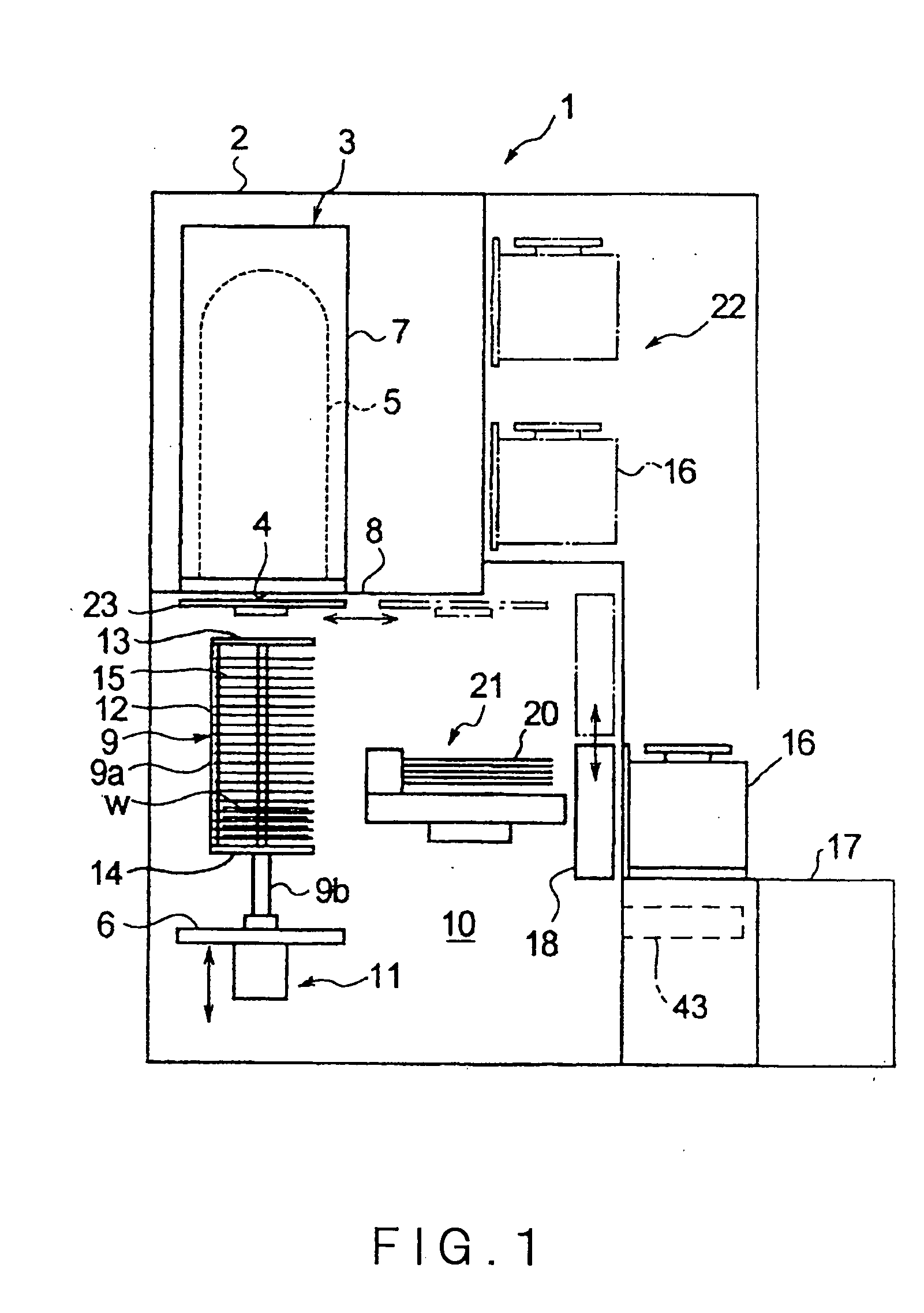
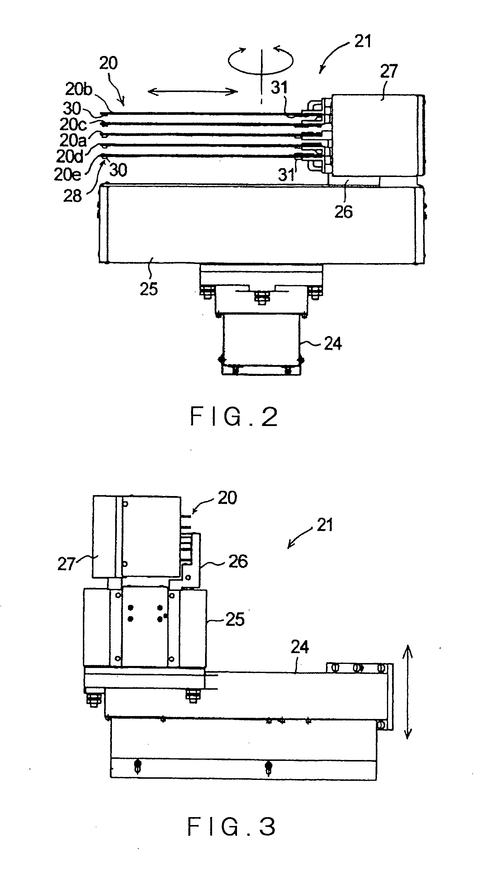
[0028] An embodiment of the present invention will be described herebelow with reference to the accompanying drawings. FIG. 1 is a longitudinal sectional view schematically showing a vertical-type heat processing apparatus in one embodiment of the present invention. FIG. 2 is a schematic view of an example of a transfer mechanism. FIG. 3 is a view of the transfer mechanism shown in FIG. 2 seen from one side.

[0029] As shown in FIG. 1, the vertical-type heat processing apparatus 1 includes a housing 2 defining a contour. In an upper area of the housing 2, there is disposed a vertical-type heat processing furnace 3 for performing a predetermined process, such as a CVD process, to an object to be processed, such as a thin disk-shaped semiconductor wafer w, contained in the heat processing furnace 3. The heat processing furnace 3 is mainly composed of: a reaction tube 5 made of quartz which is a longitudinally elongated process vessel having a lower open end as a furnace opening 4; a li...


PUM


Abstract

The present invention is a vertical-type heat processing apparatus comprising: a heat processing furnace; a holder capable of being loaded into the heat processing furnace and unloaded therefrom, with holding therein a plurality of objects to be processed at predetermined vertical intervals in a tier-like manner; a transfer mechanism including a base table capable of vertically moving and rotating, and a substrate supporter capable of horizontally moving on the base table; and a controller for controlling the transfer mechanism; wherein the transfer mechanism is adapted to transfer an object to be processed between a container containing a plurality of objects to be processed at predetermined intervals, and the holder; the substrate supporter includes a to-and-fro driving part for driving the substrate supporter in the horizontal direction, and a pitch-change driving part for changing a pitch at which the objects to be processed are supported; the controller is adapted to monitor an encoder value outputted from an encoder of the pitch-change driving part during an operation of the to-and-fro driving part of the substrate supporter; and the controller is adapted to judge upon a change of the encoder value that the transfer mechanism is abnormally driven, and then is adapted to stop the drive of the transfer mechanism.

Description

FIELD OF THE INVENTION [0001] The present invention relates to a vertical-type heat processing apparatus and a method of controlling a transfer mechanism in the vertical-type heat processing apparatus. BACKGROUND ART [0002] In the manufacture of semiconductor devices, various processing apparatuses (semiconductor manufacturing apparatuses) are employed for performing various processes such as oxidation processes, diffusion processes, and CVD (Chemical Vapor Deposition) processes, to objects to be processed such as semiconductor wafers (also referred to as “wafer” below). One of the known processing apparatuses is a heat processing apparatus of a batch type, such as a vertical-type heat processing apparatus, which is capable of simultaneously heat-processing a number of objects to be processed. [0003] The vertical-type heat processing apparatus includes: a heat processing furnace; a holder (also referred to as “boat”) capable of being carried into the heat processing furnace and carr...

Claims


Application Information

Patent Timeline
IPC IPC(8): F27D5/00
CPCF27B17/0025F27D3/0084H01L21/68707H01L21/67288H01L21/67781H01L21/67265H01L21/324Y10S414/137
Inventor ASARI, SATOSHITAKAHASHI, KIICHIOYAMA, KATSUHIKO
Owner TOKYO ELECTRON LTD
Why Eureka
Try Eureka