
Weapon detection processing

Inactive Publication Date: 2007-10-11
SMITH STEVEN WINN
View PDF7 Cites 56 Cited by
  • Summary
  • Abstract
  • Description
  • Claims
  • Application Information

AI Technical Summary

Benefits of technology

[0006] It is therefore the goal of the invention to provide an improved method and apparatus for detecting security threats and contraband concealed under the clothing of persons entering security controlled areas. Another goal of the invention is to reduce the manpower required to operate a multitude of body scanners. Yet another goal is to improve the quality and reliability of image evaluation of body scanners. Yet another goal is to prevent the image evaluation process from being compromised by bribe or threat. Still another goal is to reduce the physical space requirements around body scanners. A further goal is to improve the overall processing speed of body scanner images. A still further goal is to eliminate the potential embarrassment of subjects being screened by body scanners.

Problems solved by technology

This may be as simple as asking the subject to remove the item from within their clothing, or as invasive as a strip search.
Body scanners are capable of detecting a wide range of security threats and contraband; however, the required image interpretation presents a multitude of problems and difficulties.
The large number of security officers operating these systems, and the nature of this work, promotes errors and deficiencies in the security screening process.
For instance, security officers may become distracted or tired and miss concealed objects.
In a worse scenario, a security officer may be bribed or threatened to ignore concealed objects.
Further, the presence of the security officer unnecessarily slows the processing speed in the common case where no concealed objects are present.
Still further, many subjects express objection to an electronic image of their unclothed body being displayed and viewed by the security officer dealing with them.
Even further, the distributed and independent operation of prior art body scanners prevents the centralized storage and access of electronic data related to security screening procedures.

Method used


Image

  • Weapon detection processing
  • Weapon detection processing
  • Weapon detection processing

Examples


Embodiment Construction

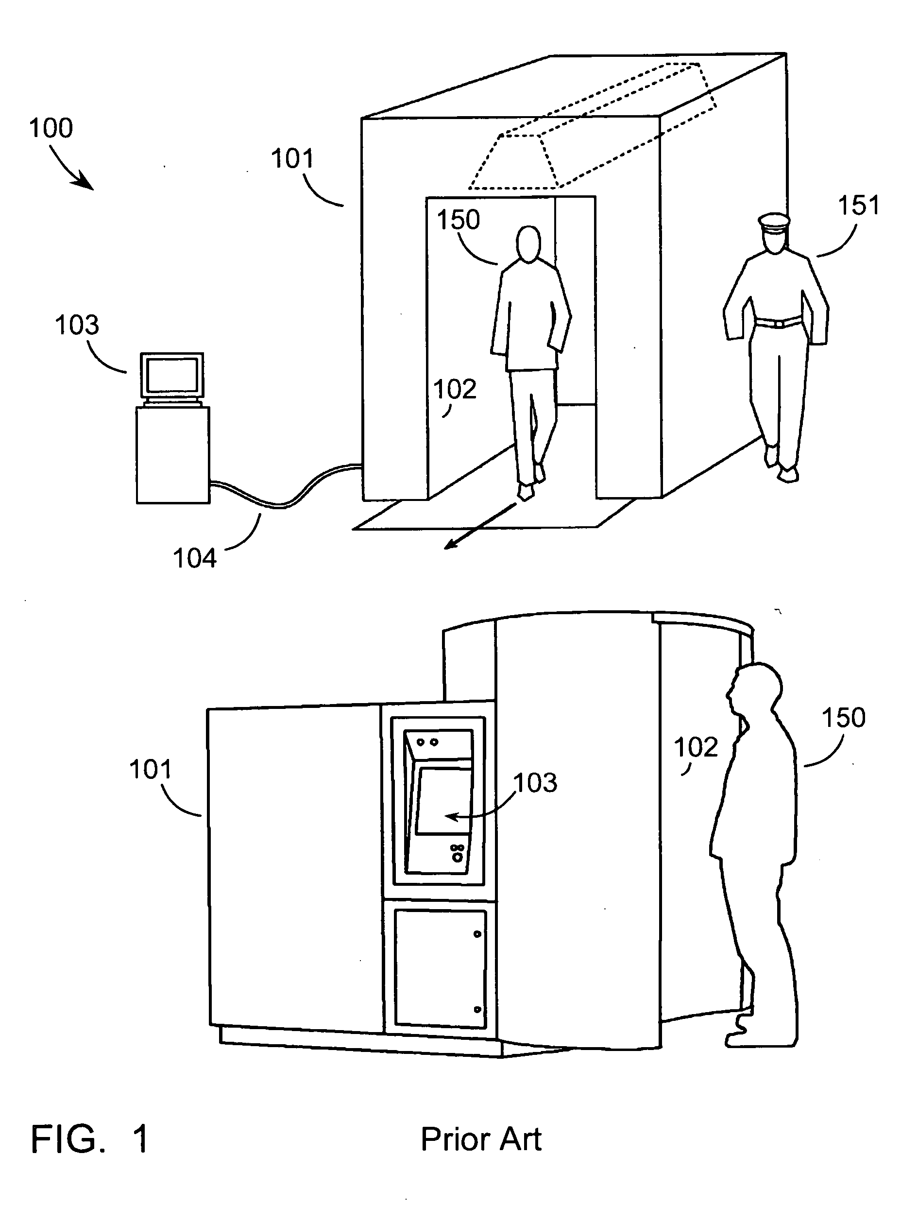
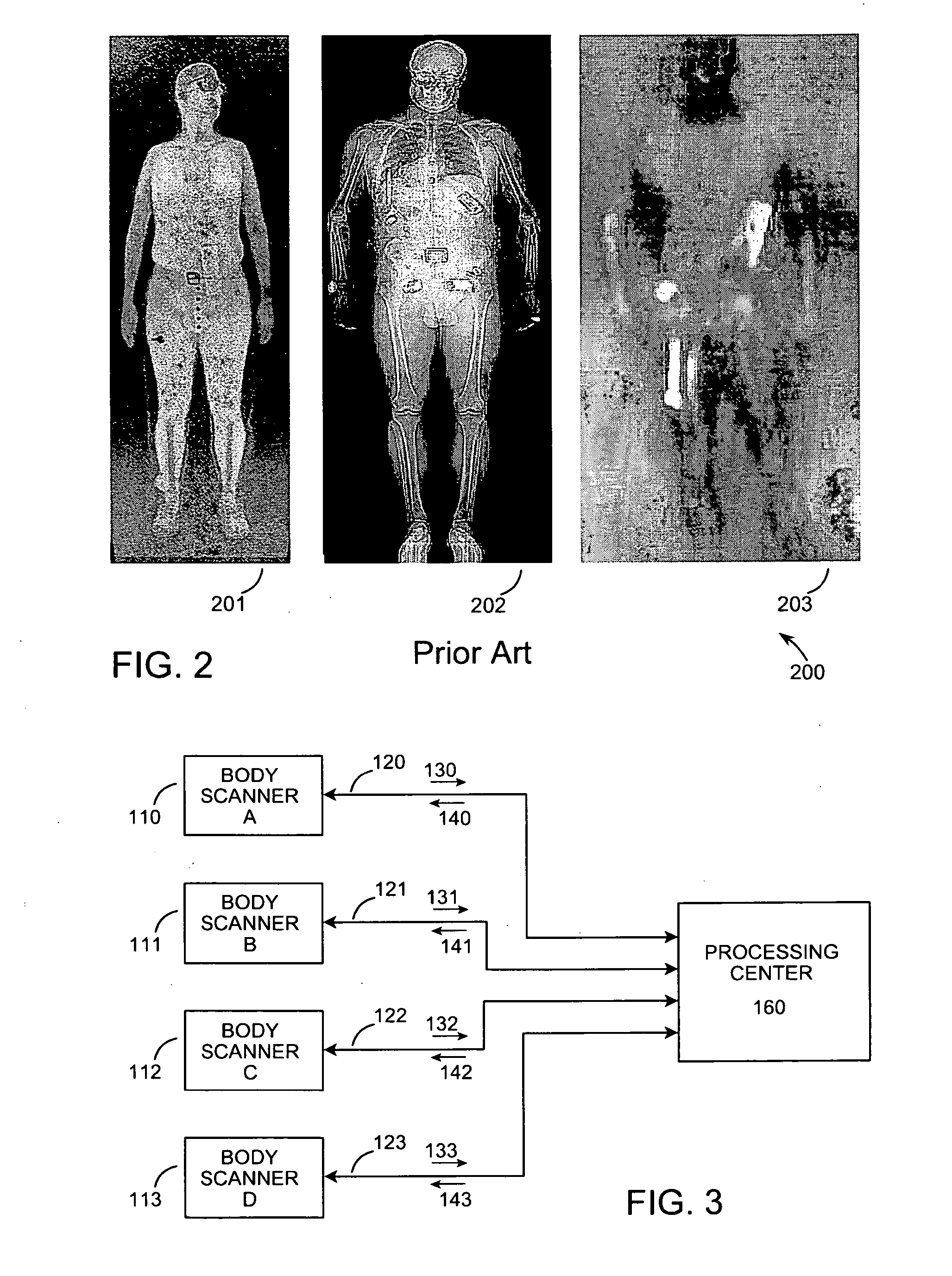
[0015]FIG. 1 shows two examples of prior art radiant energy imaging systems used to detect security threats and contraband concealed under the clothing of persons entering security areas. Commonly called “body scanners,” these systems are well known in the art and marketed by a variety of companies, as previously described. The overall body scanner 100 consists of an enclosure 101 that contains the radiant energy detector and, if needed, the radiant energy illuminator. One area on the exterior of the enclosure 101 is the imaging location 102, which is where the subject 150 being screened is positioned for the screening process. During this process the subject may be required to remain stationary, or may be allowed to walk through or by the apparatus, depending on the type of body scanner being used. The image acquisition process typically lasts a few seconds, at which time the electronic image produced by the body scanner is displayed on a computer monitor 103. The monitor 103 may b...


PUM


Abstract

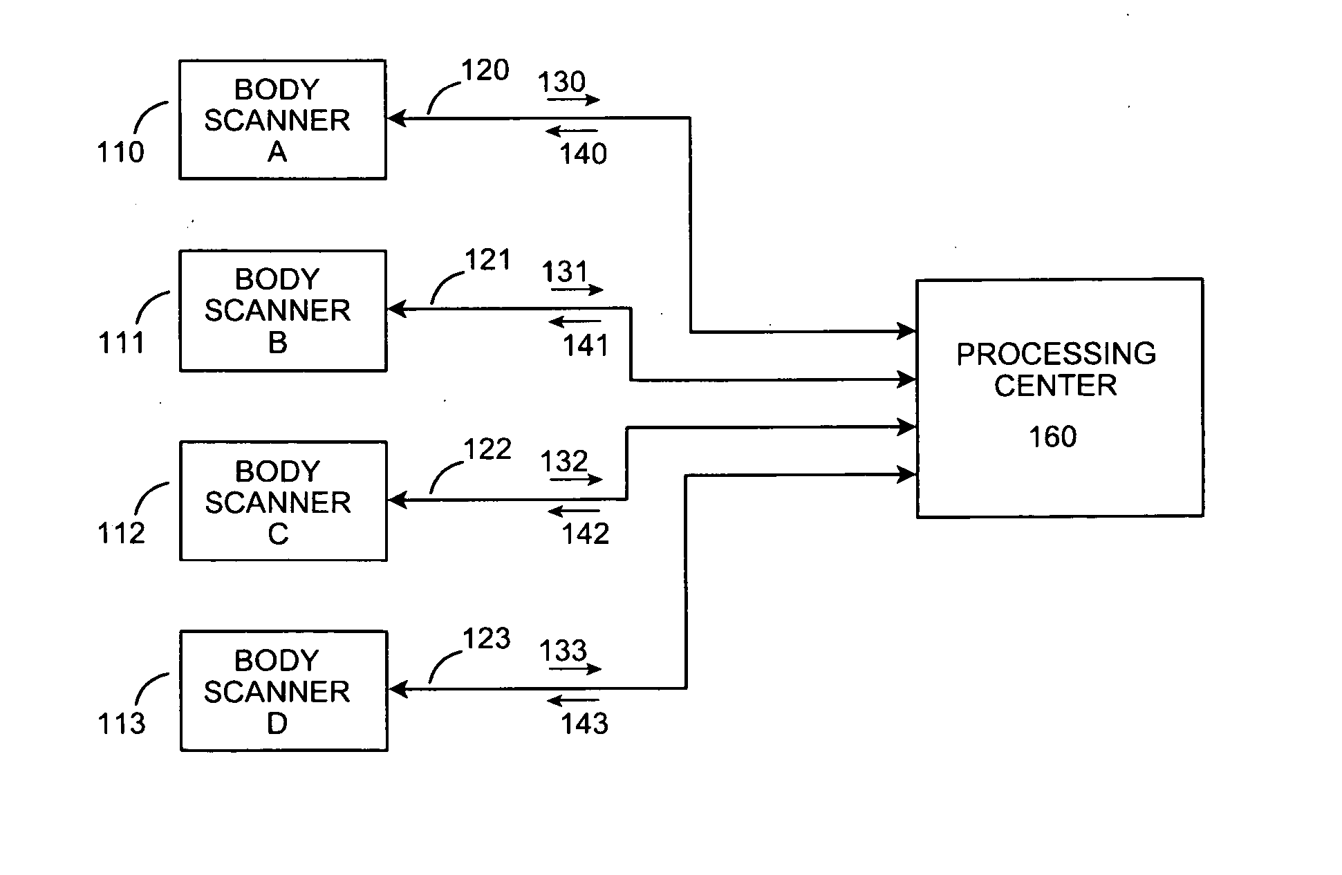
A radiant energy imaging system is used to create an electronic image of a person entering a security controlled area to detect weapons or contraband concealed under their clothing. The electronic image is electronically transmitted to a processing center where it is evaluated by a human and / or software algorithms for the presence of concealed objects. The resulting evaluation, consisting of digitally represented information, is electronically transmitted back to the examination site. In one embodiment this processed data is displayed as a graphical outline of the concealed objects superimposed on an optical image of the person. In another embodiment, the processed data is used to control a personnel barrier controlling access into the security controlled area. In another embodiment a network allocation server selectively routes the electronic images from two or more body scanners to two or more processing centers.

Description

BACKGROUND OF THE INVENTION [0001] This invention relates to the transmission, evaluation, and display of electronic images used to detect weapons concealed under persons' clothing. [0002] Over the last 20 years a variety of radiant energy imaging systems have been developed to detect weapons, explosives and contraband concealed under the clothing of persons entering security controlled areas. All of these systems operate by detecting radiant energy that has been modulated by or emitted from the body of the person being examined. Radiant energies used include: x-rays, microwaves, millimeter waves, infrared light, terahertz waves, and ultrasound. These radiant energies may be reflected from near the body surface, transmitted entirely through the body, or emitted from the body as thermal radiation. Commercial systems include the model SECURE 1000, sold by Rapiscan Security Products, Hawthorne, Calif.; model SmartCheck, sold by American Science and Engineering, Billerica, Mass., model ...

Claims


Application Information

Patent Timeline
IPC IPC(8): G01N23/04G01T1/161
CPCG01V5/0083G01V5/271
Inventor SMITH, STEVEN WINN
Owner SMITH STEVEN WINN
Learn More