
High Power Fiber Amplifier

a fiber amplifier and high-power technology, applied in fiber transmission, lasers, transmission, etc., can solve the problems of easy ruggedization, deterioration of fiber amplifier performance, and limited core diameter of fiber amplifiers, and achieve the effect of less nois

Inactive Publication Date: 2007-10-04
STATE OF ISRAEL - SOREQ NUCLEAR RES CENT
View PDF5 Cites 15 Cited by
  • Summary
  • Abstract
  • Description
  • Claims
  • Application Information

AI Technical Summary

Benefits of technology

[0014] The present invention seeks to provide a simple, efficient and low cost high-power amplifier for low-power CW single frequency amplification and low energy pulsed source (referred to herein for short, “low power low energy”).
[0016] At the low power low energy source entrance, the fiber amplifier's core size may be small enough to enable efficient low noise amplification to power levels still lower than the previously mentioned deleterious effects evolution threshold. The next amplification stages with the enlarged core may also have, but not necessarily, lower Numerical Aperture (NA), which may provide further efficient amplification to high power CW single frequency or high energy pulse amplification, without the appearance of the non-linear deleterious effects. When a single mode source is used, high beam quality may be achieved due to the high beam quality of the source and the low mode coupling along the multi-mode amplification portions [M. E. Fermann, “Single mode excitation of multimode fibers with ultra short pulses”, Optics Letters, Vol. 23, No. 1. 1998, pp. 52-54].
[0018] The fiber amplifier of the present invention is much more efficient and produces less noise stemming from ASE and non-linear effects than the prior art, when amplification of low power CW single frequency source or low energy pulsed source is required.

Problems solved by technology

In addition, they may be easily ruggedized, due to their simple arrangement.
When a low energy pulsed source should be amplified to high energy pulses by a fiber amplifier, the core diameter of the fiber amplifier is limited to a minimum value, under which the fiber amplifier performance deteriorates.
The core diameter reduction may cause elevated power density flow in the fiber, which may stimulate fiber damage or non-linear effects such as stimulated Raman or Brillouin scattering or Self Phase Modulation, which have deleterious effect on the amplified pulse.
Similar problems can also occur in CW lasers and amplifiers where nonlinear effects such as Brillouin scattering can limit the output power when operating with narrow line widths (e.g. <10 MHz).
A further restriction on the available output power from pulsed fiber is the energy storage capacity of the amplifying fiber.
On the other hand, by using a fiber with a high diameter core that supports multi-mode operation in which the deleterious effects are eliminated, a very low gain and high amplification threshold are achieved, yielding a very low efficiency amplifier.
Furthermore, when multi-mode fiber is used, a poor beam quality is achieved, which is unsuitable for applications demanding single mode or alternatively, near diffraction limited beam.
However, when low energy source amplification is required, these methods are inadequate for achieving highly efficient amplification, due to the fact that the signal amplification threshold is high (mainly because of the high saturation energy and power, resulting from the high MFD, manifested by these methods) and the high noise evolution, mainly due to the Amplified Spontaneous Emission (ASE), resulting from the high population inversion and low efficiency signal amplification.

Method used


Image

  • High Power Fiber Amplifier
  • High Power Fiber Amplifier
  • High Power Fiber Amplifier

Examples


Embodiment Construction

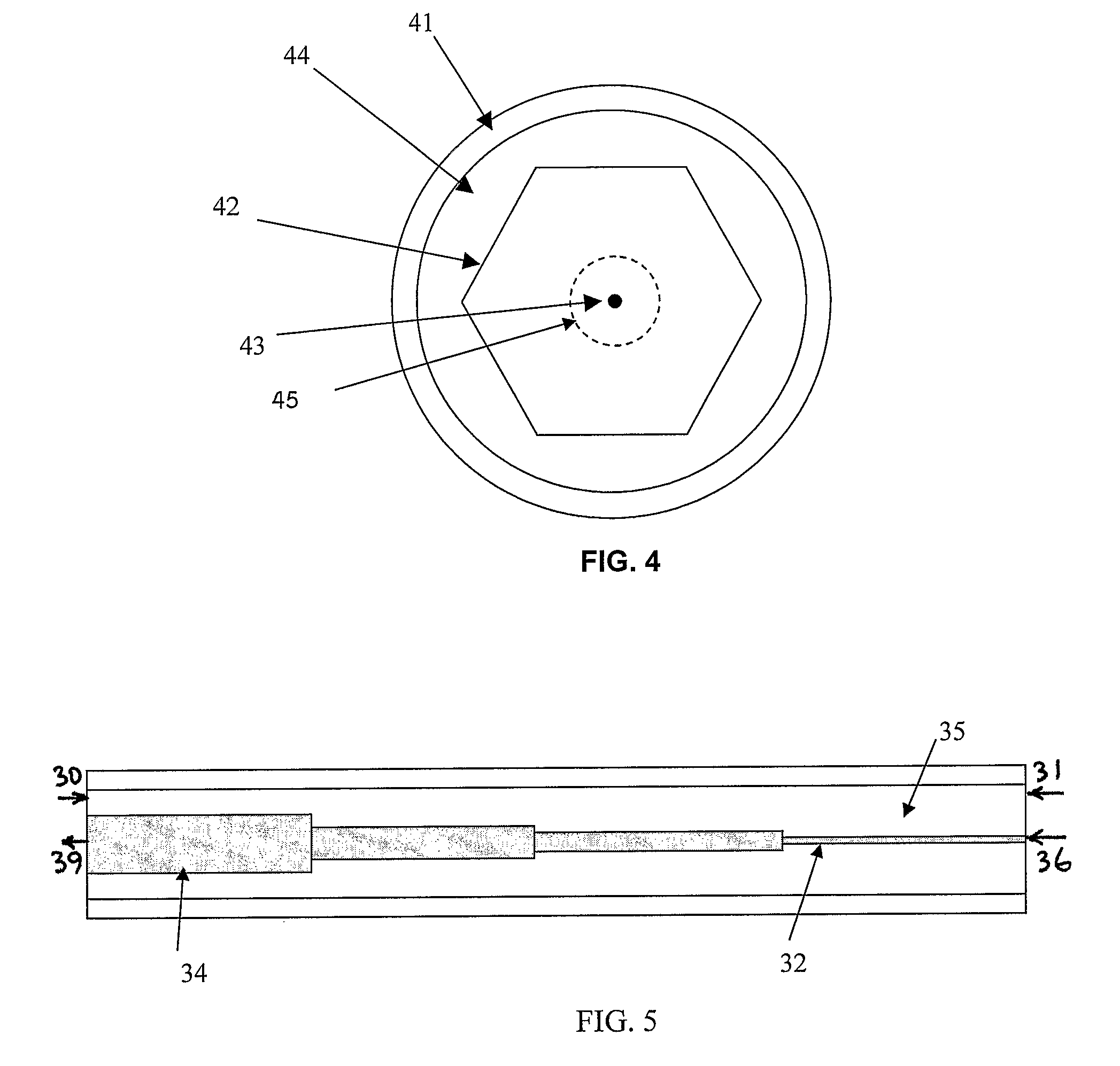
[0025] Reference is now made to FIG. 2, which illustrates a fiber amplifier for pulsed low energy source or low power single frequency CW source (low power, low energy source), such as, but not limited to, a laser diode 26. A high power laser diode 20 may pump optical power to a rare-earth doped composite double clad fiber 28.

[0026] The double clad fiber 28 cross section is shown in detail in FIG. 4. The double clad fiber may comprise, without limitation, a protective outer jacket 41, an outer clad 44, an inner clad 42 and a doped core 43, which may comprise a rare-earth doped core, such as but not limited to, Yb3+ doped silica, Er3+ doped silica, Yb3+:Er3+ doped silica, Tm3+ doped silica and Ho3+:Tm3+ doped silica fibers, or any combination thereof. The doped core 43 may be a non-polarization-maintaining core or a polarization-maintaining core, according to the intended application requirements. Additional clad layers 45 may be added between the doped core 43 and inner clad 42, cr...


PUM


Abstract

A high power fiber amplifier including a double clad fiber including a protective outer jacket (41), an outer clad (44), an inner clad (42, 35) and a doped core (43, 34, 32), and a source of pump power coupled to the inner clad through coupling optics (22) and at least one of a side-fiber coupling section and an end-fiber coupling section, wherein the inner clad includes a large diameter core portion (34), operative as a high power amplification stage, capable of absorbing the majority of the pump power, and a small diameter core portion (32), operative as a low power amplification stage, wherein both core portions, pumped through the inner clad (35), are serially connected through an optical interface point (37).

Description

FIELD OF THE INVENTION [0001] The present invention relates to high power fiber amplifiers, and methods and apparatus for achieving high energy pulses or CW (continuous wave) single frequency signals from high power fiber amplifiers, when low energy, low power source is utilized. BACKGROUND OF THE INVENTION [0002] High power fiber amplifiers have become increasingly popular due to their high efficiency, simplicity and reliability. In addition, they may be easily ruggedized, due to their simple arrangement. [0003] High power applications generally use a double clad fiber. This fiber comprises a core, usually doped with a lasing material such as rare earth ions or other materials, an inner cladding encircling the doped core, through which the pump power flows and is gradually absorbed in the doped core, and an outer cladding encircling the inner cladding and forming a dielectric wave guide for the pump signal. The optical characteristics of the inner cladding closely match high power ...

Claims


Application Information

Patent Timeline
Patent Type & Authority Applications(United States)
IPC IPC(8): H01S3/067H01S3/0941H01S3/16
CPCG02B6/262H01S3/06729H01S3/06754H01S3/1618H01S3/0941H01S3/09415H01S3/094007
Inventor SINTOV, YOAV
Owner STATE OF ISRAEL - SOREQ NUCLEAR RES CENT
Learn More