Measuring apparatus and measuring method
- Summary
- Abstract
- Description
- Claims
- Application Information
AI Technical Summary
Benefits of technology
Problems solved by technology
Method used
Image

Examples
Embodiment Construction
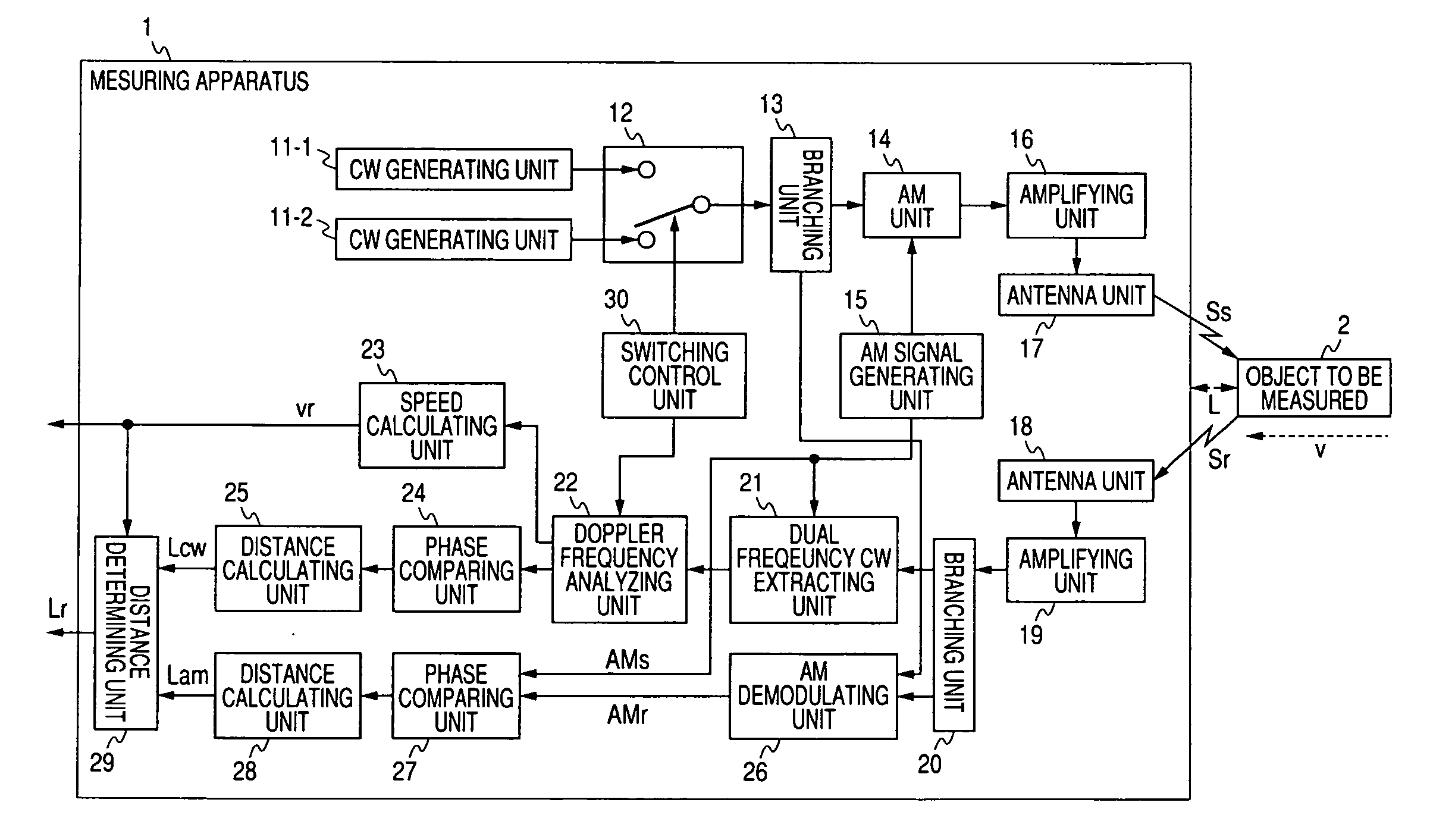
[0032]In order to facilitate an understanding of the present invention, an example of a sensor previously invented by the inventors of the present invention is explained at the outset, with reference to FIGS. 1 and 2.
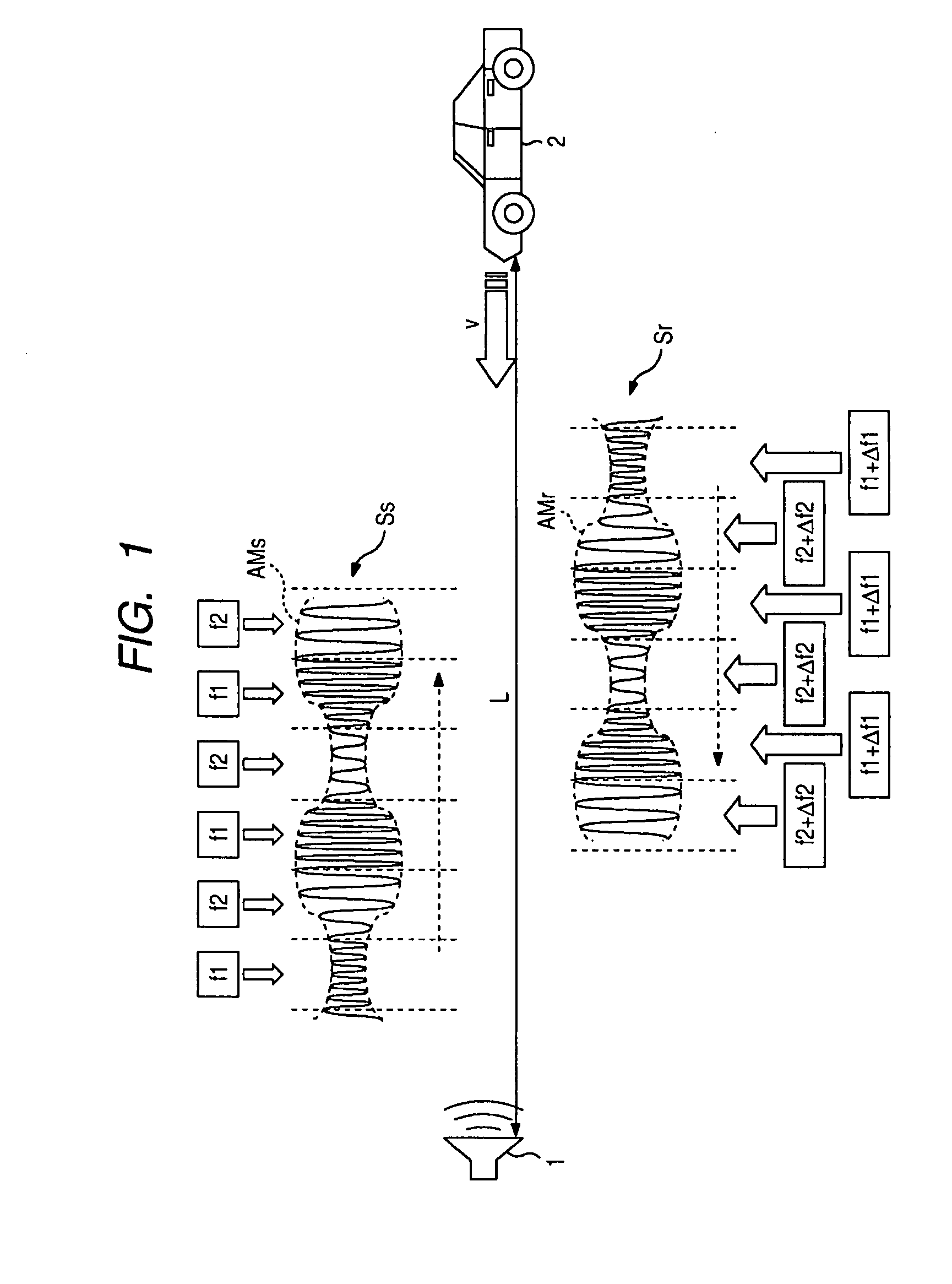
[0033]Referring initially to FIG. 1, distance is measured by using the dual frequency CW method. FIG. 1 shows a measuring apparatus 1 for producing a signal obtained by switching a CW having a frequency f1 and a CW having a frequency f2 based on time division (hereinafter “dual frequency CW”) as a carrier wave. Further, the measuring apparatus 1 modulates the amplitude of the dual frequency CW using an AM signal, and outputs the signal obtained by the amplitude modulation as a transmission signal Ss. Thus, the transmission signal Ss has two frequencies f1 and f2.
[0034]The transmission signal Ss is reflected by an object to be measured 2, and the reflection signal is received by the measuring apparatus 1 as a receipt signal Sr.
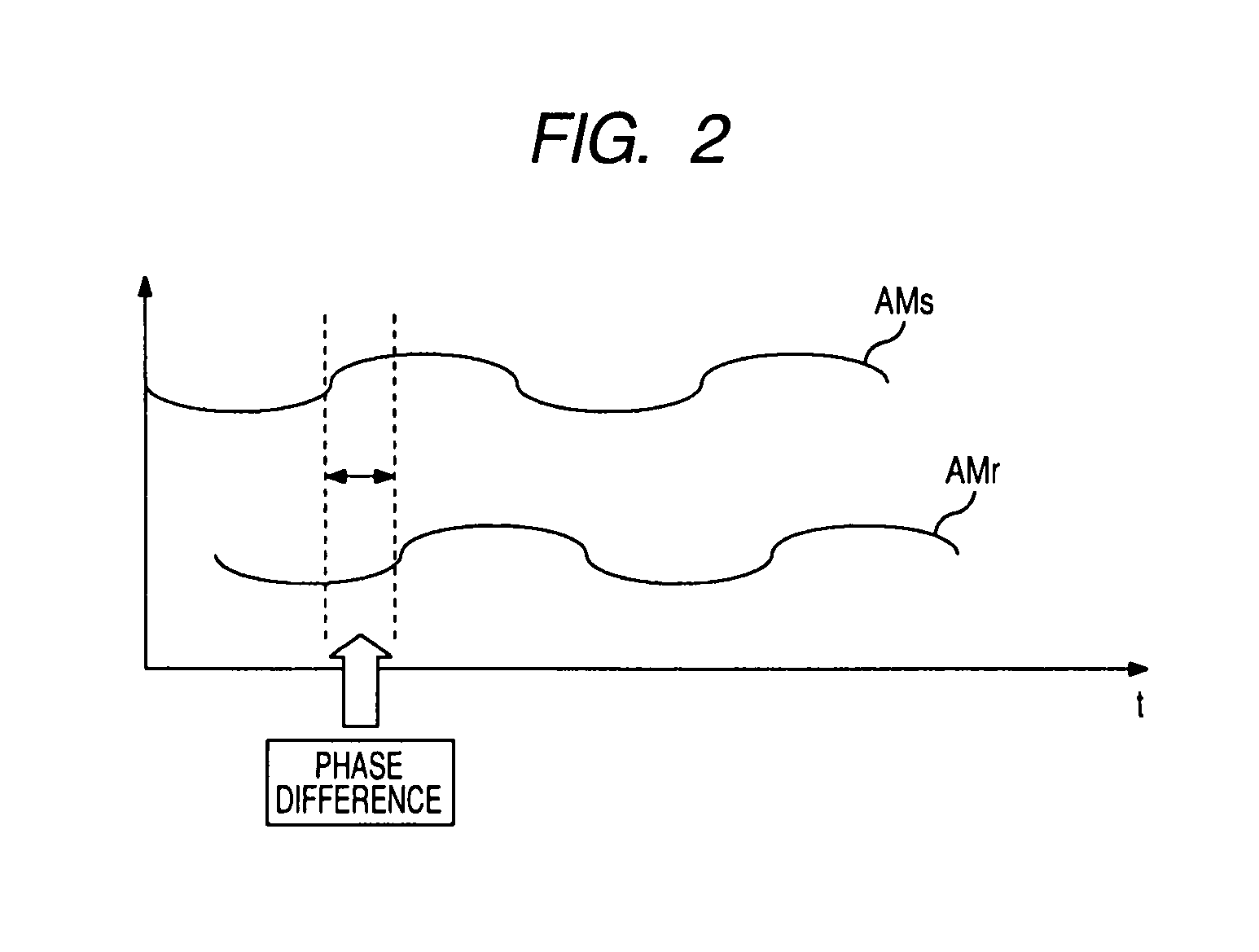
[0035]When there is a relative speed v betwe...
PUM
 Abstract
Description
Claims
Application Information
 - R&D
- Intellectual Property
- Life Sciences
- Materials
- Tech Scout
- Unparalleled Data Quality
- Higher Quality Content
- 60% Fewer Hallucinations
Browse by: Latest US Patents, China's latest patents, Technical Efficacy Thesaurus, Application Domain, Technology Topic, Popular Technical Reports.
© 2025 PatSnap. All rights reserved.Legal|Privacy policy|Modern Slavery Act Transparency Statement|Sitemap|About US| Contact US: help@patsnap.com