
Image display apparatus

a technology of image display and display screen, which is applied in the manufacture of electrode systems, electric discharge tubes/lamps, discharge tubes luminescnet screens, etc., can solve the problems of insulation film overhang collapse, high processing cost, and drop in production, and achieve the effect of higher processing cos

Inactive Publication Date: 2007-09-20
HITACHI DISPLAYS
View PDF2 Cites 1 Cited by
  • Summary
  • Abstract
  • Description
  • Claims
  • Application Information

AI Technical Summary

Benefits of technology

[0006]These types of electron sources can be arrayed in multiple columns (for example, horizontally) and multiple rows (for example, vertically) to form a matrix, and an image display device then made from numerous fluorescent elements arrayed to match the individual electron sources. Photolithographic(resist) processes are preferably not used when manufacturing the electron emitter electrode since these types of electron sources are not prone to emit electrons if there is any surface contamination on the electron emitter electrode. An undercut is therefore formed on the side wall of the supply electrode side of the electron emitter electrode, or an undercut formed on the opening on the electron emitter section of the surface protective insulator film. During forming of the emitter electrode film, the fact that there is no mask or film formed on the undercut section is utilized to cut the electrode emitter via self alignment. Electrical isolation can be performed but requires a complicated process that causes higher processing costs.
[0008]Resolving these problems, requires simplifying the structure and process for isolating the pixels, eliminating photo (resist) processes, improving the processing, preventing a drop in production due to foreign objects, and correcting electrical short defect locations.

Problems solved by technology

Electrical isolation can be performed but requires a complicated process that causes higher processing costs.
The undercut formed on the supply electrode side wall is prone to electrical shorts if there are foreign objects present which results in a drop in production.
Moreover, there is generally also a high amount of stress on the insulation film so that forming an undercut beneath the insulation film causes the insulation film overhang to collapse and leads to electrical shorts.

Method used


Image

  • Image display apparatus
  • Image display apparatus
  • Image display apparatus

Examples


Embodiment Construction

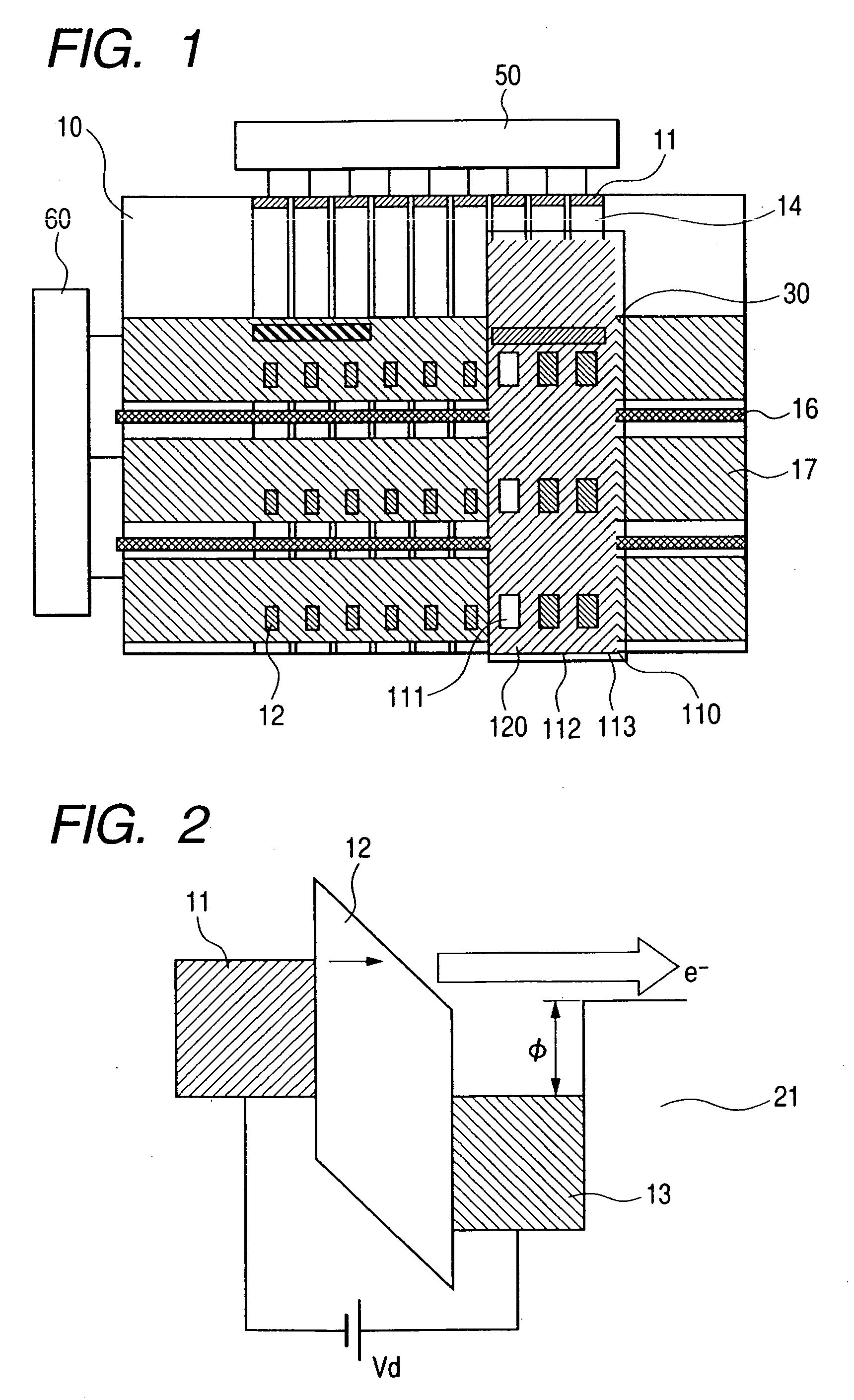
[0034]The preferred embodiments of this invention are described next while referring to the accompanying drawings. The description here utilizes the MIM type electron source as an example of an image display apparatus. However, this invention is not limited to MIM type electron sources and may be applied in the same way to image display apparatus using different types of electron emitter elements. The invention is particularly effective on hot electron type electron emitter electrodes for discharging only a portion of the element current into the vacuum.

[0035]FIG. 1 is a drawing for describing the first embodiment of this invention. FIG. 1 is a planar (flat) view showing an example of an image display device utilizing an MIM thin film electron source. FIG. 1 shows the planar surface of one substrate (cathode substrate) 10 mainly serving as the electron source. The other substrate (fluorescent element substrate, display side substrate, color filter substrate) 110 forming a portion of...


PUM


Abstract

A simple method was needed for dividing up the electron emitter electrodes into individual supply electrodes. An insulator partition wall was formed on the same layer and parallel to the supply electrode for supplying power to the electron emitter electrode, an electron emitter electrodes formed across the entire surface of the image display area, a side surface of the partition wall was sliced, condensation and solubility diffusion performed by heat treatment, ablation performed by irradiating the upper surface of the silicon partition wall with a laser, Joule thermal sealing / cutting performed by conducting electricity across the scanning lines enclosing the silicon partition wall in order to slice the electron emitter electrode.

Description

CLAIM OF PRIORITY[0001]The present application claims priority from Japanese application JP 2006-068467 filed on Mar. 14, 2006, the content of which is hereby incorporated by reference into this application.FIELD OF THE INVENTION[0002]The present invention relates to an image display apparatus and a manufacturing method for that image display apparatus, and relates in particular to an image display apparatus referred to as a flat panel display for self-light emission utilizing an electron source (field emitter) array.BACKGROUND OF THE INVENTION[0003]Image display apparatus (field emission display: FED) utilizing electron sources that are tiny and capable of circuit integration are being developed. Electron sources for this type of image display apparatus are grouped into field emission display electron sources and hot electron type electron sources. Sources such as Spindt type electron type sources, surface conduction type electron sources, and carbon nanotube type electron sources ...

Claims


Application Information

Patent Timeline
IPC IPC(8): H01J63/04H01J1/62
CPCH01J9/022H01J31/127H01J29/04
Inventor KUSUNOKI, TOSHIAKINISHIMURA, ETSUKOSAGAWA, MASAKAZUTSUJI, KAZUTAKAIKEDA, MITSUHARU
Owner HITACHI DISPLAYS
Learn More