
Vehicle Response During Vehicle Acceleration Conditions

a technology for acceleration conditions and vehicles, applied in the direction of electrical control, process and machine control, instruments, etc., can solve the problems of poor driveability, poor driveability, etc., to increase the response delay, reduce clunk, and improve driveability

Active Publication Date: 2007-09-13
FORD GLOBAL TECH LLC
View PDF18 Cites 17 Cited by
  • Summary
  • Abstract
  • Description
  • Claims
  • Application Information

AI Technical Summary

Benefits of technology

[0006]As such, in U.S. Pat. No. 6,910,990, the system controls engine torque to transition through the transmission or driveline lash zone by limiting a rate of torque increase during such conditions. In other words, when near the transmission lash zone, engine torque is adjusted at a predetermined rate until the system passes through the transmission lash zone. Further, the limiting may be adjustable based on operating conditions. By varying the limitation on the torque change in this way, driveability can be improved.
[0007]However, the inventors herein have recognized a disadvantage with such an approach. In particular, while rate limiting torque changes may reduce clunk, it may also increase a response delay to the point noticeable by the driver. Further, the greater the reduction in clunk (i.e., the more torque increases or decreases are limited), the greater the response delay.
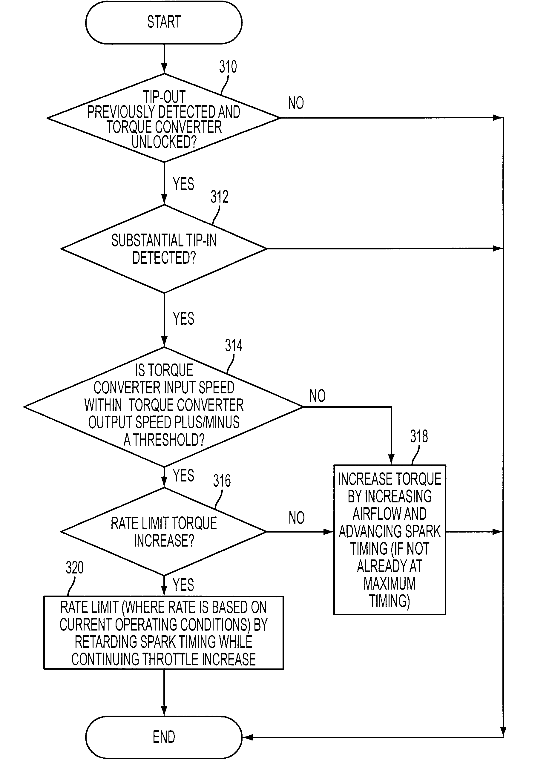
[0008]In this way, it may be possible to coordinate multiple torque actuators during a driver tip-in to both reduce clunk without substantially increasing total response time, while also providing improved operation for both slipping and non-slipping conditions. For example, by coordinating throttle and ignition timing adjustments during a driver tip-in in this way, it is possible to, in effect, increase pre-charging of the intake manifold and cylinders with airflow so that once the transition through the lash zone is complete, a more rapid torque increase is possible. As another example, by adjusting operating depending on whether slipping or non-slipping transmission conditions are present, it is possible to manage the lash transition for a fully locked transmission driveline.

Problems solved by technology

Under some conditions, there is the potential for poor driveability when the vehicle operator releases and subsequently engages the accelerator pedal.
Specifically, as described in U.S. Pat. No. 6,266,597, transmission or driveline gear lash crossing during such conditions can degrade driver feel.
This series of events produces an impact, which if transmitted to the driver is called clunk, resulting in poor driveability and customer dissatisfaction.
This disadvantage of the prior art is exacerbated when the operator returns the accelerator pedal to a depressed position, indicating a desire for increased engine torque.
However, in this situation, the engine is producing a larger amount of torque than during deceleration because the driver is requesting acceleration.
Thus, another, more severe, impact is generally experienced due to the transmission or driveline lash during the zero torque transition.
However, the inventors herein have recognized a disadvantage with such an approach.
In particular, while rate limiting torque changes may reduce clunk, it may also increase a response delay to the point noticeable by the driver.
Further, the greater the reduction in clunk (i.e., the more torque increases or decreases are limited), the greater the response delay.

Method used


Image

  • Vehicle Response During Vehicle Acceleration Conditions
  • Vehicle Response During Vehicle Acceleration Conditions
  • Vehicle Response During Vehicle Acceleration Conditions

Examples


Embodiment Construction

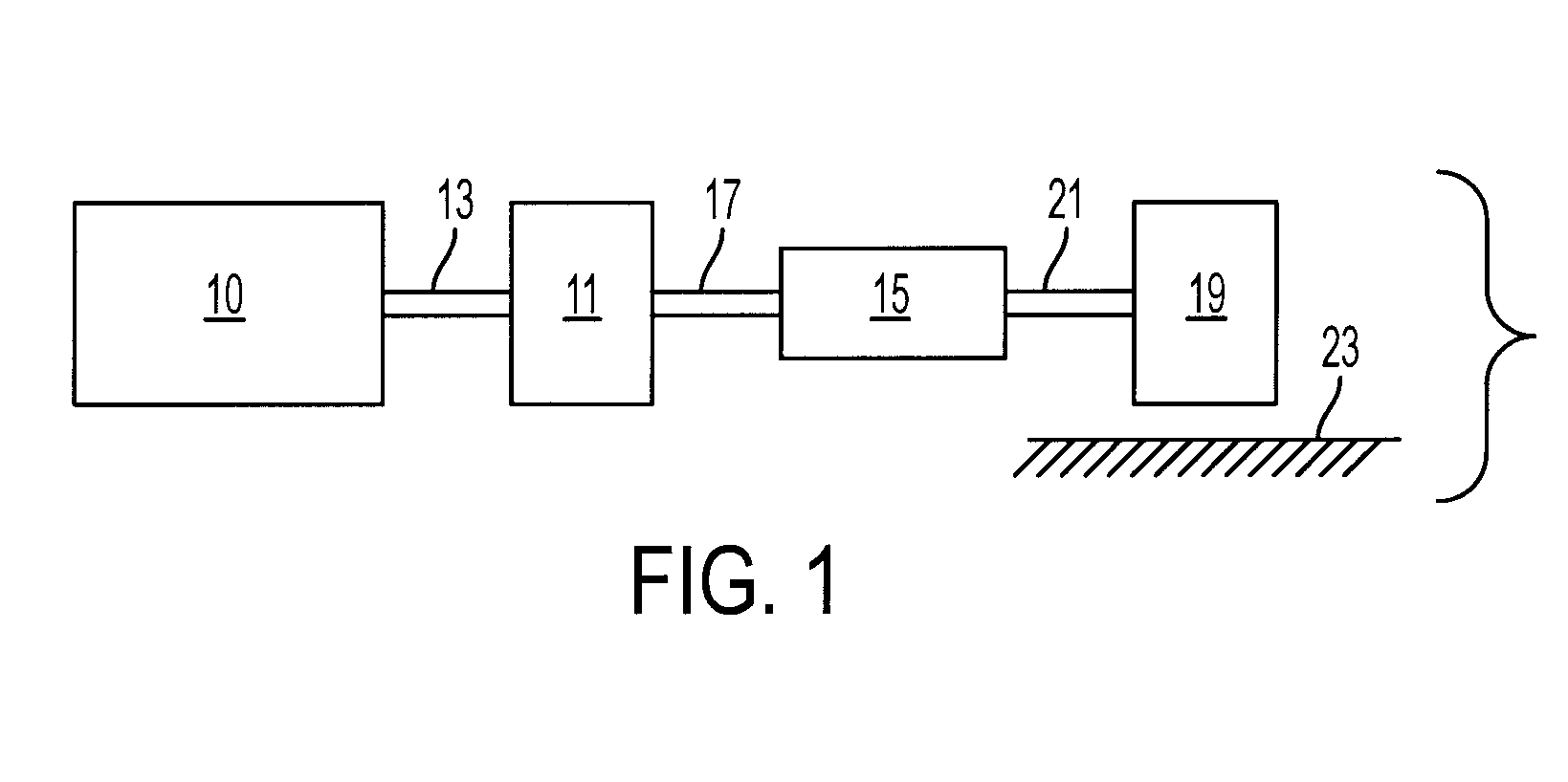
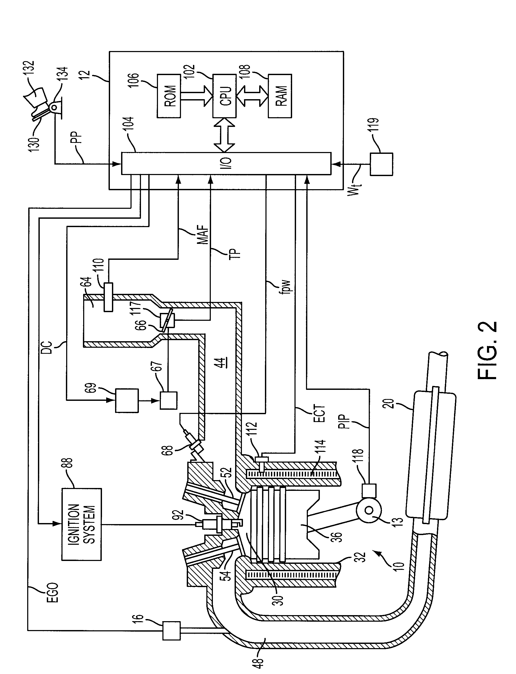
[0017]Referring to FIG. 1, internal combustion engine 10, further described herein with particular reference to FIG. 2, is shown coupled to torque converter 11 via crankshaft 13. Torque converter 11 is also coupled to transmission 15 via turbine shaft 17. Torque converter 11 has a bypass clutch (not shown) which can be engaged, disengaged, or partially engaged. When the clutch is either disengaged or being disengaged, the torque converter is said to be in an unlocked state. Turbine shaft 17 is also known as transmission input shaft.

[0018]In one embodiment, transmission 15 comprises an electronically controlled transmission with a plurality of selectable discrete gear ratios. Transmission 15 may also comprises various other gears, such as, for example, a final drive ratio (not shown). Alternatively, transmission 15 may be a continuously variable transmission (CVT). In still another example, transmission 15 may be a manual transmission, an automated manual transmission, a powershift t...


PUM


Abstract

A vehicle control method for transitioning through transmission lash regions is described using a variety of information, such as, for example, gear ratio, clutch slippage, etc. Further, different adjustment of spark and throttle angle is used to provide a rapid torque response while still reducing effects of the lash. Finally, transitions taking into account both slipping and non-slipping transmissions are described.

Description

[0001]The present application is a continuation-in-part of U.S. patent application Ser. No. 11 / 370,400, filed Mar. 7, 2006, Attorney Docket No. 81136900, entitled “System and Method for Improved Vehicle Response During Vehicle Acceleration Conditions”, the entire contents of which are incorporated herein by reference.FIELD[0002]The present application relates to engine and vehicle control, and in one example relates to operation during vehicle acceleration following deceleration.BACKGROUND AND SUMMARY[0003]Internal combustion engines are controlled in many different ways to provide acceptable driving comfort during all operating conditions. Some methods use engine output, or torque, control where the actual engine torque is controlled to a desired engine torque through an output adjusting device, such as with an electronic throttle, ignition timing, or various other devices.[0004]Under some conditions, there is the potential for poor driveability when the vehicle operator releases a...

Claims


Application Information

Patent Timeline
IPC IPC(8): G06F17/00
CPCF02D41/0002F02D41/0215F02D41/187F02D2011/102F02D2200/0404Y10T477/67F02D2250/18F02D2400/12F02P5/1504Y02T10/46Y02T10/42F02D2200/1004Y02T10/40
Inventor DOERING, JEFFRIEDLE, BRADCIARROCHI, ROBKWONG, HANKROLLINGER, JOHNPAGE, FREDERICKTRAVIS, JEFF
Owner FORD GLOBAL TECH LLC
Learn More