
Apparatus and method for a waveguide with an index profile manifesting a central dip for better energy extraction

Inactive Publication Date: 2007-09-06
LOCKHEED MARTIN CORP
View PDF29 Cites 26 Cited by
  • Summary
  • Abstract
  • Description
  • Claims
  • Application Information

AI Technical Summary

Benefits of technology

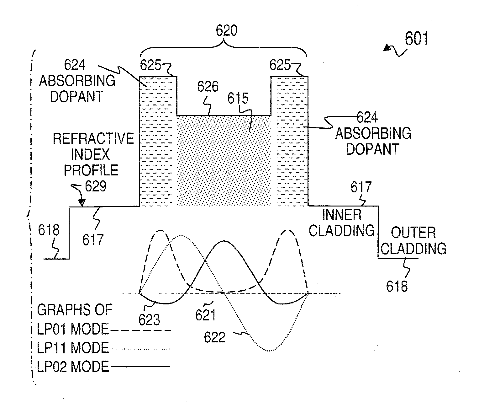
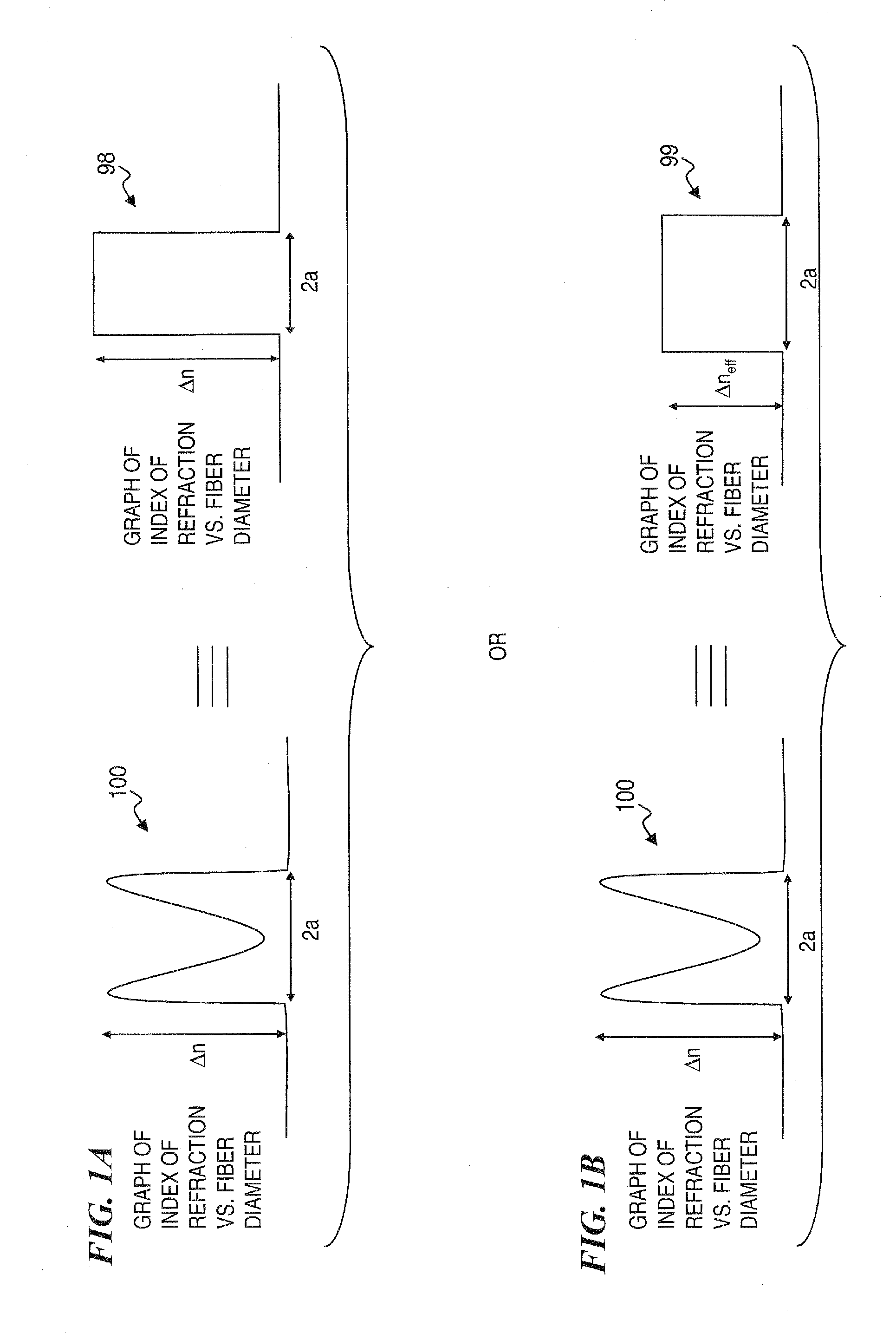
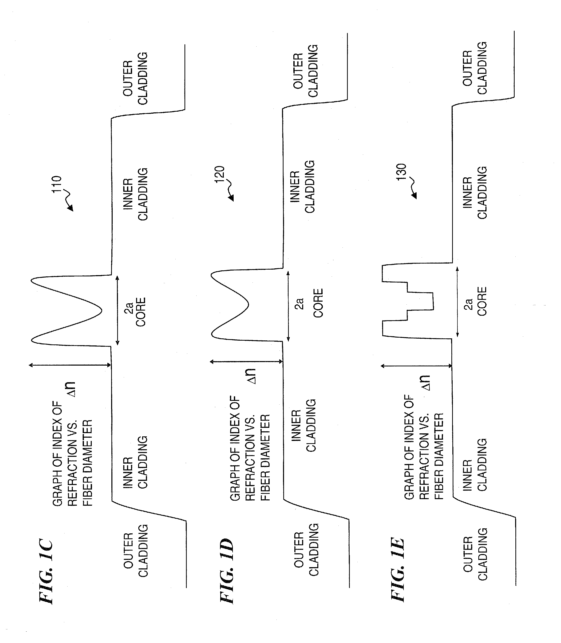
[0008] In some embodiments, the present invention utilizes a gain medium in the form of a gain fiber that has a refractive index with a significant central dip. The benefits of this central dip are apparent when an input beam is akin to that of a Gaussian mode. In some embodiments, the core is of a relatively large diameter (e.g., 20 microns or more), and the mode (i.e., the primary mode) of the signal has a relatively large cross-sectional area (LMA or large mode area) in the large core. In some embodiments, a linear-polarization-02 (LP02) mode is used such that the primary mode fills the relatively large core and e

Problems solved by technology

A high doping density may be desirable for good pump absorption in a short length, but may lead to energy losses related to quenching processes, (e.g. caused by clustering of laser-active ions and energy transport to defects).
Despite the benefits associated with fiber lasers, there are problems associated with these types of lasers.
For example, complicated temperature-dependent polarization evolution, the various nonlinear effects of which often limit the performance, and risk of fiber damage at high powers (commonly known as “fiber fuse”).
The problems of temperature-dependent polarization and fiber fuse become even more acute, given the current and proposed uses of fiber lasers.

Method used


Image

  • Apparatus and method for a waveguide with an index profile manifesting a central dip for better energy extraction
  • Apparatus and method for a waveguide with an index profile manifesting a central dip for better energy extraction
  • Apparatus and method for a waveguide with an index profile manifesting a central dip for better energy extraction

Examples


Embodiment Construction

[0038] Although the following detailed description contains many specifics for the purpose of illustration, a person of ordinary skill in the art will appreciate that many variations and alterations to the following details are within the scope of the invention. Accordingly, the following preferred embodiments of the invention is set forth without any loss of generality to, and without imposing limitations upon the claimed invention.

[0039] In the following detailed description of the preferred embodiments, reference is made to the accompanying drawings that form a part hereof, and in which are shown by way of illustration specific embodiments in which the invention may be practiced. It is understood that other embodiments may be utilized and structural changes may be made without departing from the scope of the present invention.

[0040] The leading digit(s) of reference numbers appearing in the Figures generally corresponds to the Figure number in which that component is first intr...


PUM


Abstract

A method and apparatus is described that use an index-of-refraction profile having a significant central dip in refractive index (or another tailored index profile) within the core of a gain fiber or a gain waveguide on a substrate. The benefits of this central dip (more power with a given mode structure) are apparent when an input beam is akin to that of a Gaussian mode. In some embodiments, the invention provides a fiber or a substrate waveguide having an index profile with a central dip, but wherein the device has no doping. Some embodiments use a central dip surrounded by a higher-index ring in the index of refraction of the core of the fiber, while other embodiments use a trench between an intermediate-index central core portion and the ring, or use a plurality of rings and / or trenches. Some embodiments use an absorber in at least one core ring.

Description

CROSS-REFERENCE TO RELATED APPLICATION [0001] This application claims benefit of U.S. Provisional Patent Application No. 60 / 733,977 filed on Nov. 3, 2005, titled “APPARATUS AND METHOD FOR A WAVEGUIDE WITH AN INDEX PROFILE MANIFESTING A CENTRAL DIP FOR BETTER ENERGY EXTRACTION,” which is incorporated herein by reference in its entirety.FIELD OF THE INVENTION [0002] The invention relates to fiber lasers and amplifiers, and more particularly to optical fiber gain media having a central dip or reduction in index of refraction and / or doping concentration of the active laser species such as erbium and. / or ytterbium, in order to provide higher optical-power output. BACKGROUND OF THE INVENTION [0003] Fiber lasers are typically lasers with optical fibers as gain media, although some lasers with a semiconductor gain medium and a fiber cavity have also been called fiber lasers. In most cases, the gain medium is a fiber doped with rare-earth ions such as erbium, neodymium, ytterbium, or thulium...

Claims


Application Information

Patent Timeline
IPC IPC(8): G02B6/028G02B6/02H01S3/00H04B10/12G02B6/00
CPCG02B6/02023G02B6/03605G02B6/03611G02B6/03633H01S3/06729G02B6/03661G02B6/03688G02B6/03694G02B6/03638
Inventor MINELLY, JOHN D.SAVAGE-LEUCHS, MATTHIAS P.JENSON, BARTON J.HENRIE, JASON D.EISENBERG, ERIC C.
Owner LOCKHEED MARTIN CORP
Learn More