Advanced surface discharge lamp systems

Inactive Publication Date: 2007-09-06
PHOENIX SCI & TECH
View PDF17 Cites 4 Cited by
  • Summary
  • Abstract
  • Description
  • Claims
  • Application Information

AI Technical Summary

Benefits of technology

[0008] Also, for certain combinations of high intensity and pulse length, material is evaporated from the dielectric, thereby limiting the useful lifetime of the lamp.
[0018] Further aspects of the present invention provide a means for initiating the plasma discharge along the dielectric substrate that ensures the generation of a uniform plasma, a specific electrical polarity configuration for practical use, as well as a configuration for operating a lamp at high energy while minimizing stress on high voltage switches needed to operate the lamp.

Problems solved by technology

Furthermore, SD lamps known-in-the-art employ seals (such as between the dielectric substrate and the electrodes) that utilize materials such as those commonly used for o-rings, which degrade over time, limiting practical lamp life.
Methods known-in-the-art for sealing existing lamps such as flashlamps are not adequate for all the seals in SD lamps.
Also, for certain combinations of high intensity and pulse length, material is evaporated from the dielectric, thereby limiting the useful lifetime of the lamp.

Method used


Image

  • Advanced surface discharge lamp systems
  • Advanced surface discharge lamp systems
  • Advanced surface discharge lamp systems

Examples


Embodiment Construction

[0026] In a surface discharge (SD) lamp, a plasma discharge is created by applying an electric potential that has sufficient magnitude to cause electronic breakdown of a discharge gas between two spaced apart electrodes near a dielectric surface. The resulting electronic discharge creates plasma streamers that emit intense incoherent light.

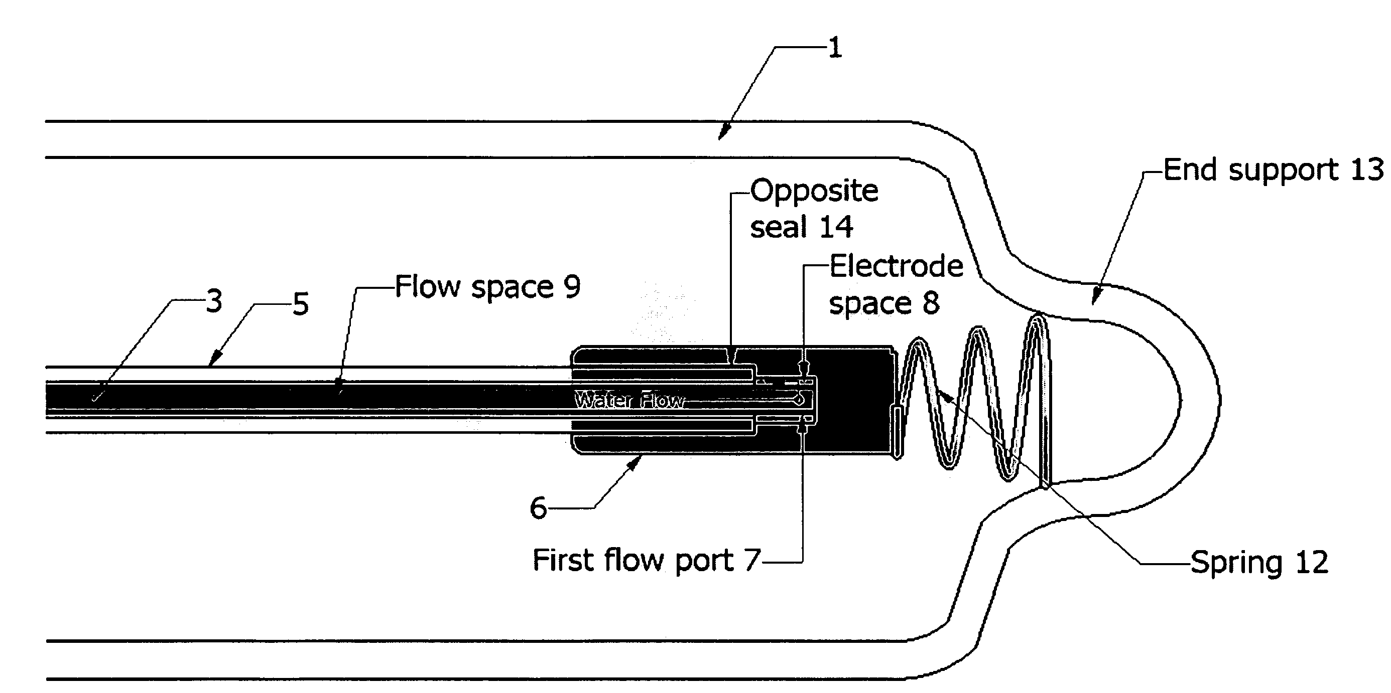
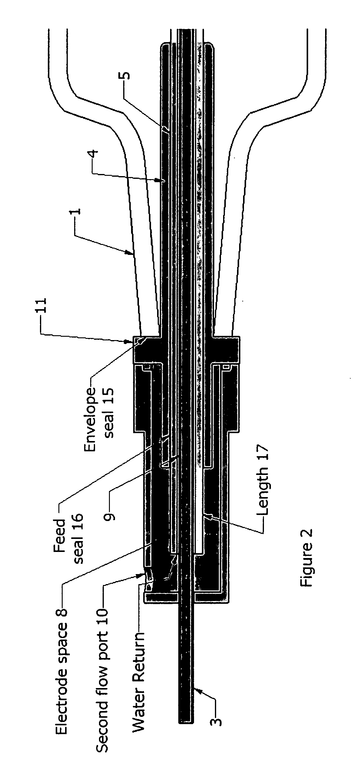
[0027] The present invention is directed to an SD lamp having electrical, cooling and support feed throughs and functions at one end of the lamp so that the entire structure of the lamp terminates at the other end of the lamp. This approach allows the SD lamp to be used when it is desirable for the lamp to be held at one end, or where the presence of electrical or cooling lines at both ends of the lamp is a complication. This approach may also be less expensive and more straightforward to implement. This allows the use of SD lamps, for instance, in water treatment applications where an array of UV lamps is attached at one end to an arm and in wat...


PUM


Abstract

A high intensity surface discharge pulsed light source system includes a dielectric substrate, a first electrode near the dielectric substrate, a second electrode spaced from the first electrode and near the dielectric substrate, with containment for a discharge gas. The system is electrically powered and cooled from a single end. The discharge volume is sealed from the environment for long operational life, and the surface material chosen to allow for high intensity operation. Reflective coatings are employed to increase the light available for practical use. A pulsed electric discharge circuit provides practical operation for long and safe operation.

Description

GOVERNMENT SUPPORT [0001] The invention was supported in part in an Advanced Technology Program under National Institute of Standards and Technology (NIST), Cooperative Agreement No. 70NANB1H3053. The Government has certain rights in the invention.BACKGROUND [0002] Pulsed lamps are used in a wide variety of commercial, military, industrial, academic, medical and environmental applications, including treatment of contaminated water, industrial effluent and air, disinfection of water, juice and foods, air and other materials and objects, laser excitation, paint stripping, curing, photography, decontamination, strobes, beacons, and the like. In commercial flashlamps, stored electrical energy is deposited into a gas between two electrodes enclosed in a transparent envelope. The electrical discharge produces plasma that is a source of radiant energy with a spectrum that can range from the infrared, to the visible and ultraviolet regions of the spectrum. The envelope serves to confine the...

Claims


Application Information

Patent Timeline
IPC IPC(8): H01J17/04
CPCH01J61/80H01J61/52
Inventor SCHAEFER, RAYMOND B.GALLAGHER, JOHNGRAPPERHAUS, MICHAEL
Owner PHOENIX SCI & TECH
Why Eureka
Try Eureka