Fluorescent lamp

A fluorescent lamp and phosphor technology, applied in the field of fluorescent lamps, can solve the problems of maintaining illuminance, degradation, and difficulty in maintaining stability for a long time, and achieve the effects of extending service life, increasing light output, and high light stability

Inactive Publication Date: 2012-04-04
USHIO DENKI KK
View PDF2 Cites 0 Cited by
  • Summary
  • Abstract
  • Description
  • Claims
  • Application Information

AI Technical Summary

Problems solved by technology

[0006] However, in the above-mentioned fluorescent lamps, since the phosphor is exposed to the discharge space, it is easy to degrade, and it is difficult to maintain the illuminance stably for a long time.
As the main cause of phosphor degradation, impurity gas (H 2 O.CO 2 etc.), especially when the dielectric barrier discharge is used, because of the discharge principle, the discharge is formed in the direction transverse to the light-emitting tube, so the damage of the phosphor is large and it is difficult to obtain sufficient photostability.

Method used


Image

  • Fluorescent lamp
  • Fluorescent lamp
  • Fluorescent lamp

Examples


Embodiment Construction

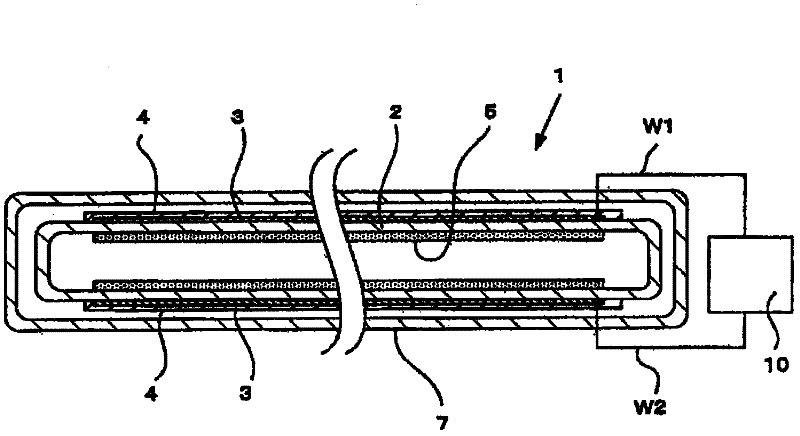
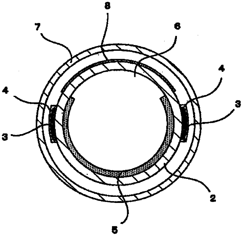
[0022] figure 1 It is a sectional view of the fluorescent lamp of this invention.

[0023] In this figure, a fluorescent lamp 1 is provided with a pair of external electrodes 3 and 3 facing each other on the outer peripheral surface of a light emitting tube 2 . The external electrodes 3, 3 have a substantially band-like shape extending in the direction of the tube axis, and pass through a conductive film such as a silver paste mixed with silver (Ag) and fritted glass, or a gold paste mixed with gold (Au) and fritted glass. form.

[0024] The external electrodes 3, 3 are covered with protective films 4, 4 made of glass layers, and the external electrodes 3, 3 are respectively connected with wires W1, W2, which are connected to a power source 10 for generating a high-frequency voltage.

[0025] The luminous tube 2 is made of synthetic quartz glass having high transmittance to vacuum ultraviolet light with a wavelength of 200 nm or less. Furthermore, in order to improve the ul...


PUM


Abstract

The invention provides a fluorescent lamp. The fluorescent lamp comprises a light-emitting tube made of quartz glass and having discharge gas including xenon packaged inside; a pair of electrodes formed on the length direction of the light-emitting tube and opposed through a dielectric medium; and an inner fluorescent body layer formed on the inner surface of the light-emitting tube. An opening part with no inner fluorescent body layer formed thereon is formed on a part on the circumferential direction of the light-emitting tube. The fluorescent lamp which can provide a fluorescent body layer which will not degrade can obtain a structure for stable light outputting. The fluorescent lamp is characterized in that an external tube is equipped in a way to cover the light-emitting tube; and an external fluorescent body layer is formed on the outer surface corresponding to the light-emitting tube and the opening part.

Description

technical field [0001] The invention relates to a fluorescent lamp, in particular to a fluorescent lamp emitting vacuum ultraviolet light. Background technique [0002] Conventionally, it is preferable to use ultraviolet rays for photochemical reactions, sterilization, decomposition of organic substances, and the like. A low-pressure mercury lamp is often used as a light source of the ultraviolet rays, but recently, as in JP-A-2001-015078 (Patent Document 1), fluorescent lamps utilizing dielectric barrier discharge have also been proposed. [0003] In the fluorescent lamp described in this patent document 1, a rare gas is sealed inside a luminous tube, and by generating a discharge that interposes a dielectric between a pair of electrodes, the rare gas is excited to emit ultraviolet light (vacuum ultraviolet light), and the luminous gas is excited on the inner surface of the luminous tube. The phosphor formed on the entire surface can obtain ultraviolet light in a predeterm...

Claims


Application Information

Patent Timeline
IPC IPC(8): H01J61/35H01J61/12
CPCH01J61/16H01J61/34H01J61/44
Inventor 田川幸治
Owner USHIO DENKI KK
Why Eureka
Try Eureka