Discrete bootstrapping in an optical receiver to prevent signal feedback

Active Publication Date: 2007-08-30
II VI DELAWARE INC
View PDF12 Cites 19 Cited by
  • Summary
  • Abstract
  • Description
  • Claims
  • Application Information

AI Technical Summary

Benefits of technology

[0017] The present invention has been developed in response to the above and other needs in the art. Briefly summarized, embodiments of the present invention are directed to an optical receiver assembly that is configured to avoid the introduction of feedback in an electrical signal converted by the assembly. In one embodiment, an optical receiver assembly is disclosed, comprising a capacitor, an optical detector provided with a power supply being mounted on the capacitor, and an amplifier mounted on a top electrode of the reference surface. The assembly further includes an isolator interposed between the reference surface and the capacitor. The isolator includes a bottom layer of dielectric material that is affixed to a portion of the reference surface and a metallic top plate that is electrically coupled both to a ground of the amplifier and to the capacitor. This configuration “bootstraps” the amplifier ground to the amplifier input via the photodiode and top electrode of the capacitor, and by so doing, allows feedback signals present at the amplifier ground to be transmitted to the amplifier input via the photodiode, which desirably cancels the feedback signal in the circuit.
[0018] Configuration of the optical receiver assembly as described above in one embodiment further reduces parasitic capacitance and inductance that may otherwise be present in the circuits of the assembly.

Problems solved by technology

Despite their utility, packages such as TO packages that house photodiodes or other optical detectors can suffer from performance-related challenges.
One of these challenges is signal feedback.
This amplification is performed by a signal amplifier, such as a transimpedance amplifier, and the amplification of the output signal produced by the amplifier can be significant when compared to the original strength of the converted photodiode signal, which can result in a certain amount of feedback.
Such feedback is unintended and can represent a significant limitation in terms of performance of the package, e.g. frequency response.
Should the feedback exceed minimal levels, oscillation can occur, which undesirably destroys any functionality of the package and requires scrapping of the part.

Method used


Image

  • Discrete bootstrapping in an optical receiver to prevent signal feedback
  • Discrete bootstrapping in an optical receiver to prevent signal feedback
  • Discrete bootstrapping in an optical receiver to prevent signal feedback

Examples


Embodiment Construction

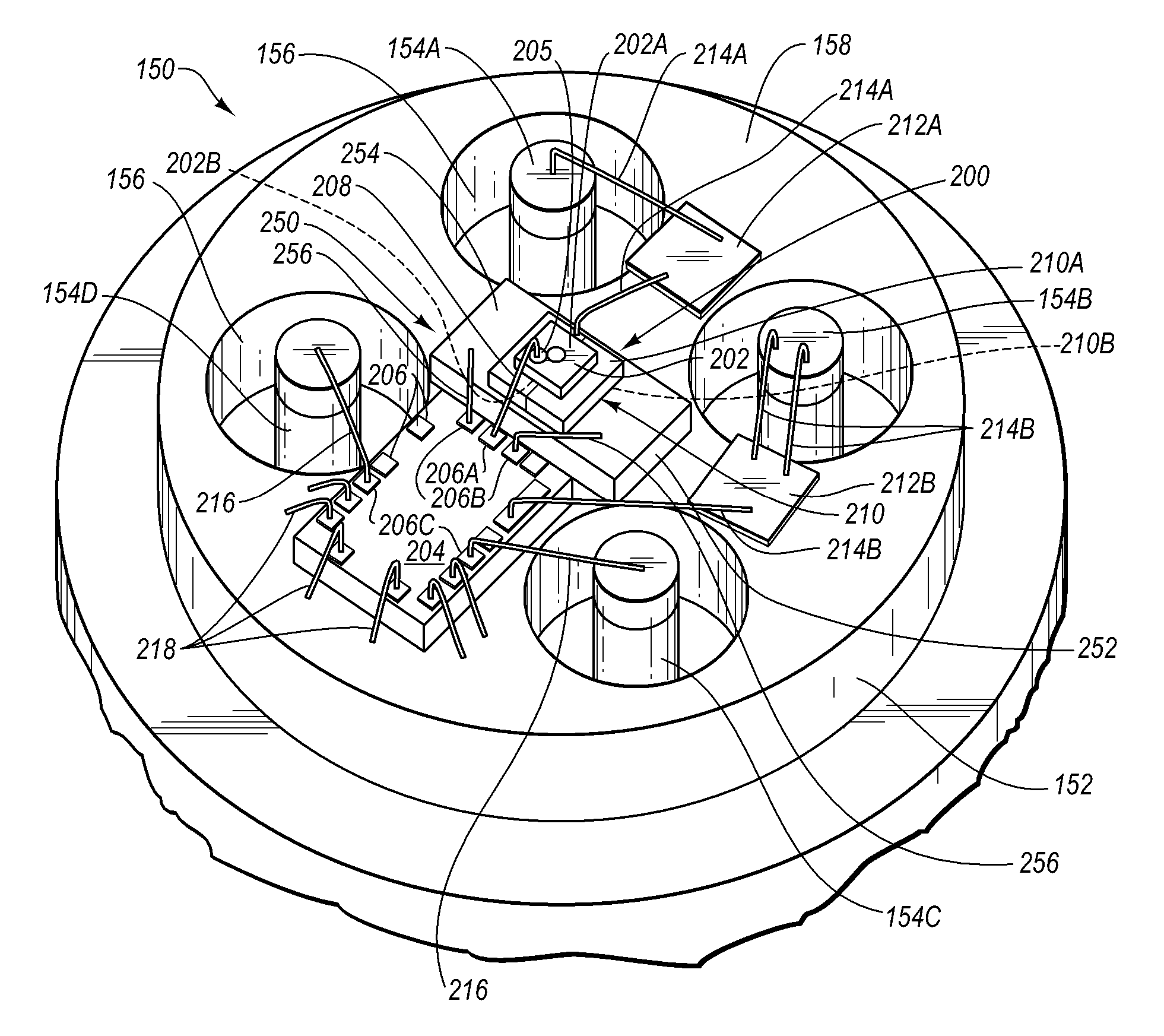
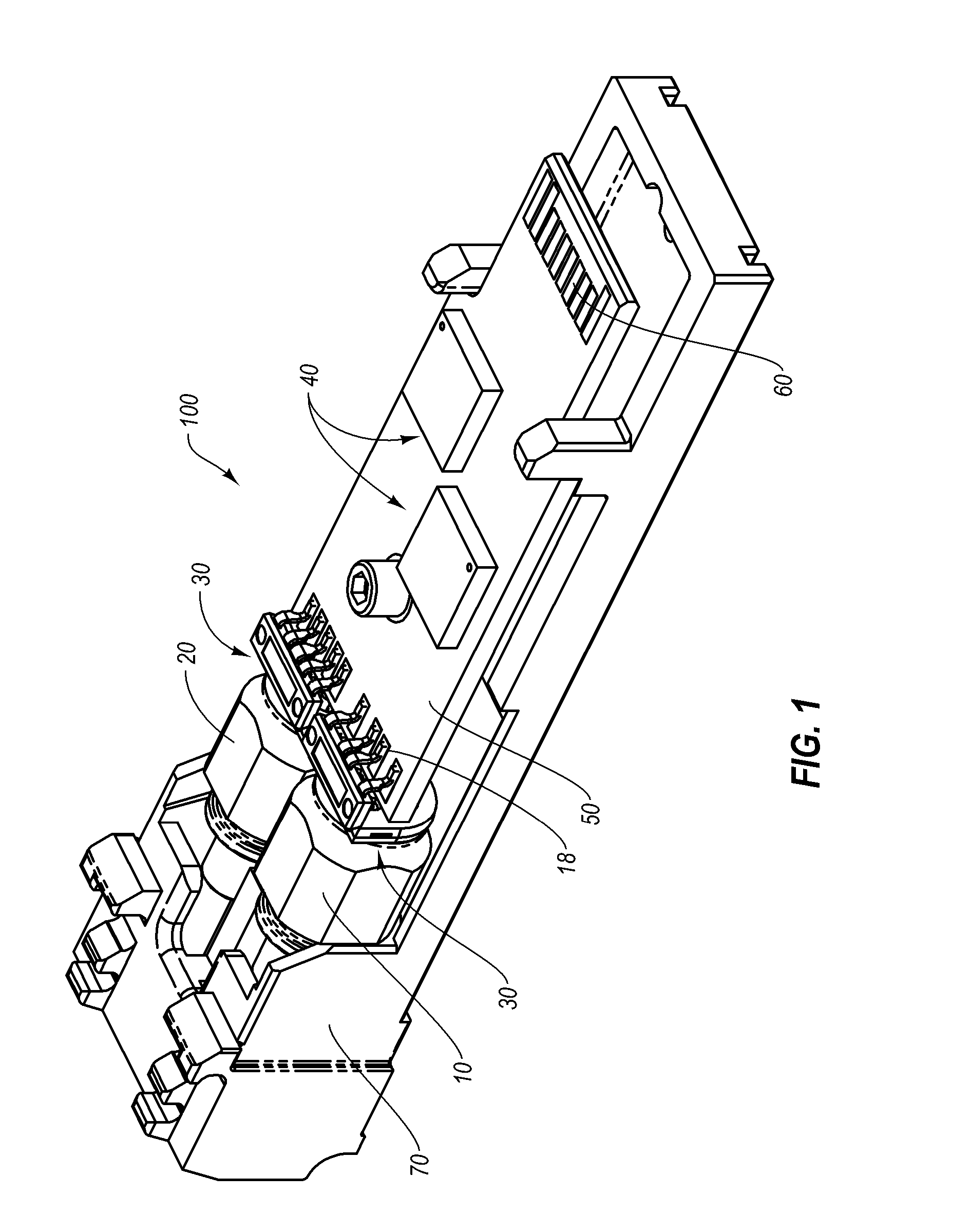
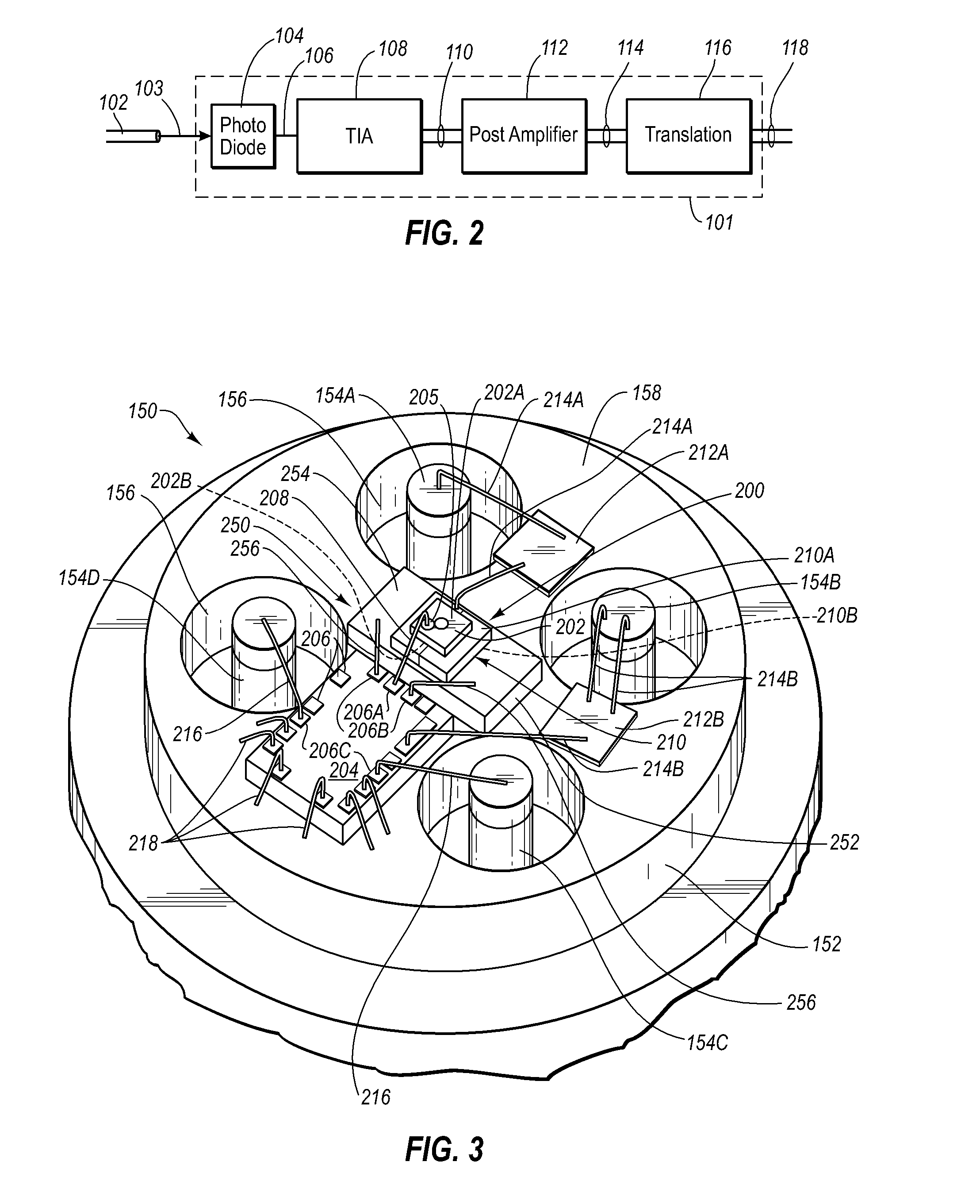
[0027] Reference will now be made to figures wherein like structures will be provided with like reference designations. It is understood that the drawings are diagrammatic and schematic representations of exemplary embodiments of the invention, and are not limiting of the present invention nor are they necessarily drawn to scale.

[0028]FIGS. 1-5 depict various features of embodiments of the present invention, which is generally directed to an optical receiver assembly that is configured to avoid the introduction of feedback in an electrical signal converted by the assembly. Reduction or elimination of signal feedback in the optical receiver assembly enables optimization of the assembly and assurance of acceptable signal integrity for its use within a communications network, for example. Embodiments of the optical receiver assembly can be included in optoelectronic packages, including TO packages that form a component of an optical subassembly for an optical transceiver module. Such ...


PUM


Abstract

An optical receiver assembly that is configured to avoid the introduction of feedback in an electrical signal converted by the assembly is disclosed. In one embodiment, an optical receiver assembly is disclosed, comprising a capacitor, an optical detector provided with a power supply being mounted on a top electrode of the capacitor, and an amplifier mounted on the reference surface. The assembly further includes an isolator interposed between the reference surface and the capacitor, wherein the isolator includes a bottom layer of dielectric material that is affixed to a portion of the reference surface, and a metallic top plate that is electrically coupled both to a ground of the amplifier and to the capacitor. This configuration bootstraps the amplifier ground to the amplifier input via the photodiode top electrode of the capacitor to cancel out feedback signals present at the amplifier ground.

Description

CROSS-REFERENCE TO RELATED APPLICATIONS [0001] This application claims the benefit of the U.S. Provisional Patent Application No. 60 / 774,787, filed Feb. 17, 2006, and entitled “DISCRETE BOOTSTRAPPING IN AN OPTICAL RECEIVER TO PREVENT SIGNAL FEEDBACK,” which is incorporated herein by reference in its entirety.BACKGROUND [0002] 1. Technology Field [0003] The present invention generally relates to receivers used to detect optical signals in an optical communications network. In particular, the present invention relates to a discrete bootstrapping configuration for an optical receiver that reduces the incidence of feedback of a signal received by the optical receiver. [0004] 2. The Related Technology [0005] Fiber-optics and optoelectronics are important aspects of modern optical networks because they allow for efficient, accurate and rapid transmission of optical data between various components in the network system. An optical transceiver module (“transceiver”) is an example of a modul...

Claims


Application Information

Patent Timeline
IPC IPC(8): H04B10/06H04B10/43
CPCG02B6/4246H04B10/66H01L31/0203H01L31/0232H01L31/107H01L2224/48137H01L2224/4823H01L2224/48237H01L2924/01004H01L2924/01046H01L2924/01057H01L2924/01079H01L2924/14H01L2924/19041H01L2924/30107H01L2924/3011G02B6/4292H04B10/60G02B6/42H01L31/02
Inventor DOUMA, DARIN JAMES
Owner II VI DELAWARE INC
Why Eureka
Try Eureka