
High efficiency, high power cryogenic laser system

Inactive Publication Date: 2007-08-30
NORTHROP GRUMMAN SYST CORP
View PDF7 Cites 4 Cited by
  • Summary
  • Abstract
  • Description
  • Claims
  • Application Information

AI Technical Summary

Benefits of technology

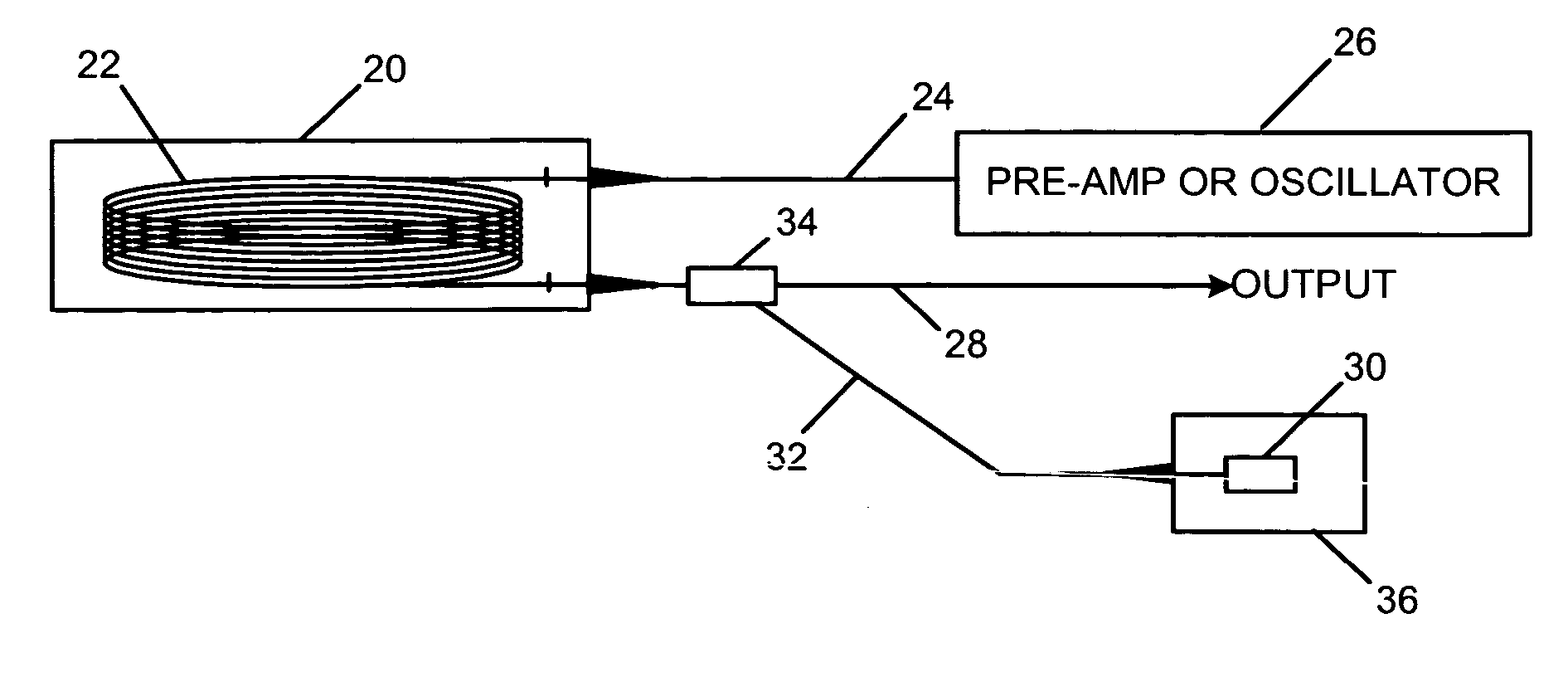
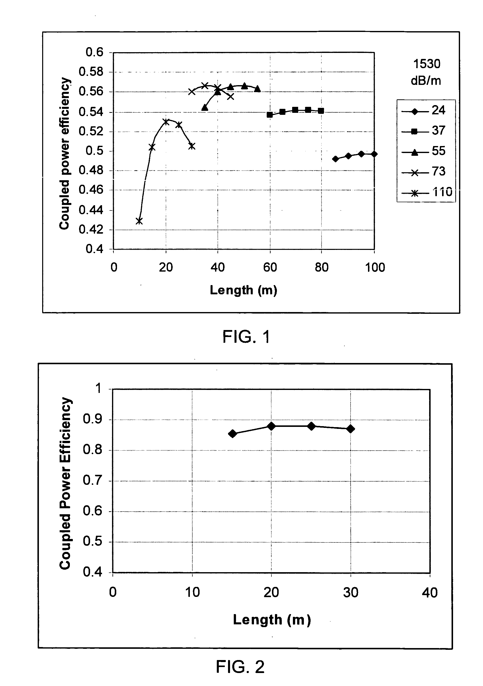
[0005] Briefly, and in general terms, the high power cryogenic fiber laser system of the invention comprises at least one fiber laser amplifier; means for coupling an input optical signal to the fiber laser amplifier; optical pump means for coupling power into the fiber laser amplifier; and means for cryogenically cooling the fiber laser amplifier, resulting in enhanced optical slope efficiency. In one embodiment of the invention, the fiber laser amplifier comprises a thulium doped fiber; and the laser system produces output at an eye-safe wavelength, with a slope efficiency of at least approximately 80%. In another embodiment, the fiber laser amplifier comprises an erbium doped fiber; and the laser system produces output with a slope efficiency of approximately 90%.
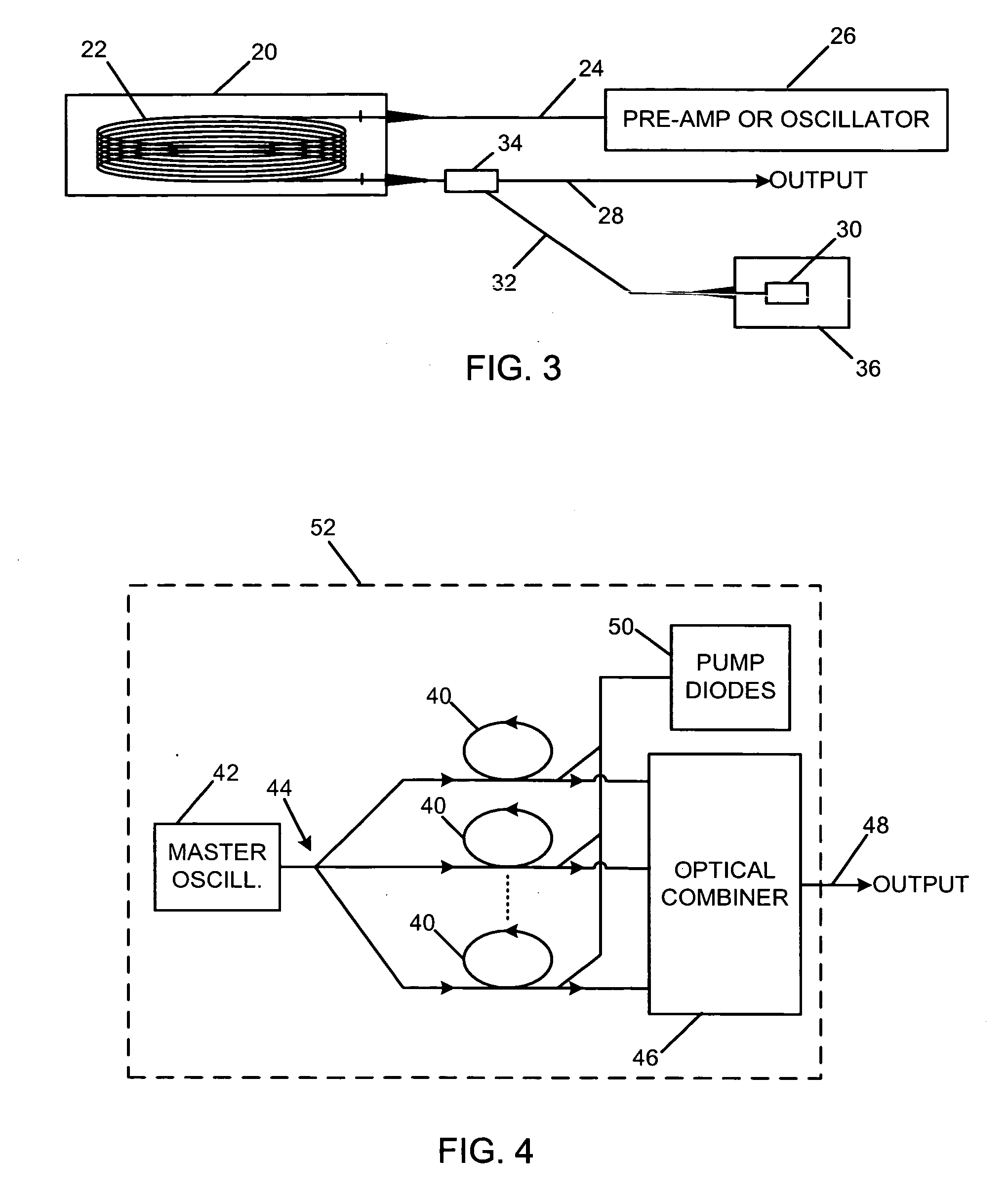
[0006] The invention may also be defined as a high power cryogenic fiber laser system capable of operation at high efficiency levels, the system comprising a plurality of fiber laser amplifiers; a master oscillator for generating an input optical signal at a desired wavelength; means for coupling the input optical signal to the plurality of fiber laser amplifiers; a plurality of laser pump diodes; means for coupling power from the laser pump diodes into the plurality of fiber laser amplifiers; means for cryogenically cooling the plurality of fiber laser amplifiers, resulting in enhanced optical slope efficiency; and means for optically combining the outputs of the plurality of fiber laser amplifiers, to produce a single coherent optical output.
[0008] The invention may also be defined as a method for generating a high power laser beam from a cryogenic fiber laser system capable of operation at high efficiency levels, the method comprising the steps of providing a plurality of fiber laser amplifiers; generating in a master oscillator an input optical signal at a desired wavelength; coupling the input optical signal to the plurality of fiber laser amplifiers; powering a plurality of laser pump diodes; coupling power from the laser pump diodes into the plurality of fiber laser amplifiers; cryogenically cooling the plurality of fiber laser amplifiers, resulting in enhanced optical slope efficiency; and optically combining the outputs of the plurality of fiber laser amplifiers, to produce a single coherent optical output. The method may also comprise cryogenically cooling other components of the fiber laser system, such as the pump diodes and optical components used in the step of optically combining the outputs of the fiber laser amplifiers.

Problems solved by technology

Unfortunately, achieving efficiencies this high is much more difficult for wavelengths in the “eye-safe” region above 1.3 μm.

Method used


Image

  • High efficiency, high power cryogenic laser system
  • High efficiency, high power cryogenic laser system
  • High efficiency, high power cryogenic laser system

Examples


Embodiment Construction

[0014] As shown in the drawings for purposes of illustration, the present invention is concerned with a high power, high efficiency cryogenic fiber laser system. As is well known, output beams from multiple fiber lasers may be combined to produce a single coherent beam of high power, which has both commercial and military applications. As is also well known, fiber lasers function as amplifiers when pumped with optical energy launched into each fiber laser. Unfortunately, fiber lasers produced or proposed prior to this invention do not achieve desirably high levels of efficiency, which may be measured, for example, by the ratio of the output optical power to the input pump power. A useful measure in this regard is the slope efficiency, which is the slope of a characteristic curve plotting the output power to the input pump power. This is due to the fact that each laser has a threshold pump power below which no lasing occurs, such that the slope efficiency at some point on the curve i...


PUM


Abstract

A fiber laser system and a related method for its use, in which one or more fiber laser amplifiers are cryogenically cooled and optimized to operate at a desirably high efficiency. Versions of the laser system using either thulium or erbium doped fibers are disclosed. In a high power version of the system, the outputs of multiple fiber lasers are coherently combined. Cooling by a selected liquefied gas, such as nitrogen, is applied to the fiber laser amplifiers and, optionally, to pump diodes and to optical elements used to combine the outputs of the fiber laser amplifiers.

Description

BACKGROUND OF THE INVENTION [0001] This invention relates generally to high power lasers and, more particularly, to techniques for achieving high power and high efficiency in fiber lasers. Achieving high efficiency in fiber lasers has long been a goal for designers of high power laser systems employing fiber lasers. A convenient measure of efficiency is optical-to-optical slope efficiency, which is the slope of a characteristic curve plotting optical output power against optical input pump power. This curve is basically a straight line once the pump power reaches a threshold value at which lasing begins. It is known that an ytterbium (Yb) doped fiber laser pumped at 975 nm wavelength can operate at slope efficiency of approximately 80% for an output wavelength near 1080 nm. Unfortunately, achieving efficiencies this high is much more difficult for wavelengths in the “eye-safe” region above 1.3 μm. For example, an erbium:ytterbium (Er:Yb) codoped fiber laser has achieved a slope effi...

Claims


Application Information

Patent Timeline
IPC IPC(8): H01S3/30H01S3/04
CPCH01S3/0407H01S3/06754H01S3/094003H01S5/02423H01S3/1608H01S3/1616H01S3/2383H01S3/0941
Inventor ROTHENBERG, JOSHUA ELLIOTTBROSNAN, STEPHEN JOHNEPP, PAUL THOMAS
Owner NORTHROP GRUMMAN SYST CORP
Learn More