
Phosphor, production method hereof and light emitting instrument

Active Publication Date: 2007-08-23
NAT INST FOR MATERIALS SCI
View PDF1 Cites 22 Cited by
  • Summary
  • Abstract
  • Description
  • Claims
  • Application Information

AI Technical Summary

Benefits of technology

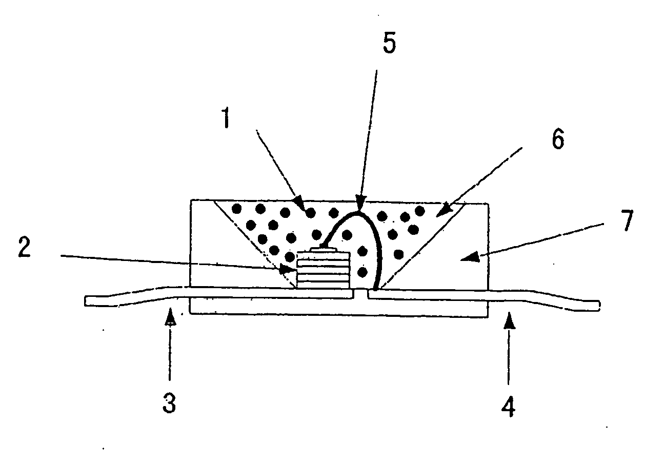
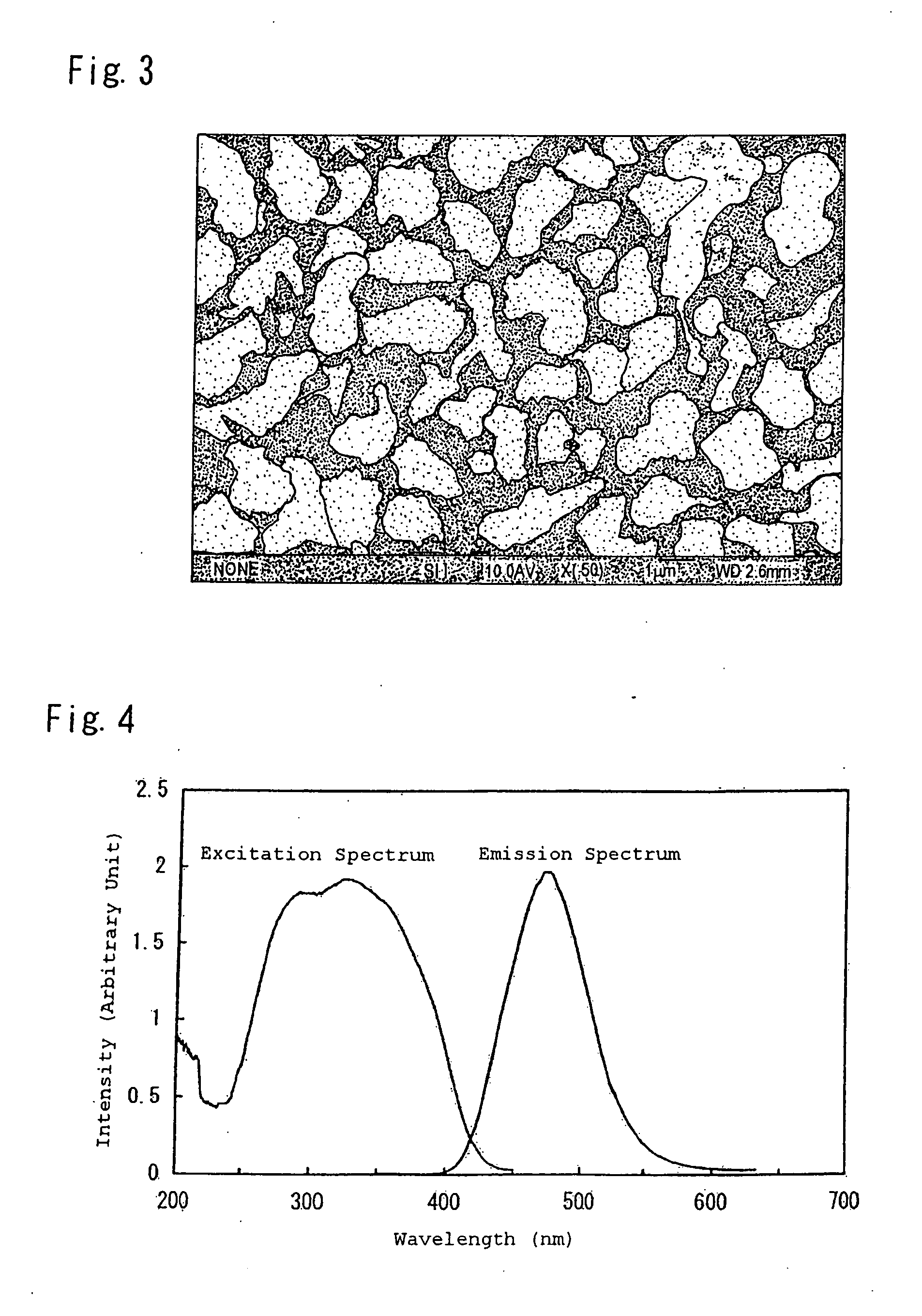
[0086] The phosphors of the present invention each contain, as a main component, an AlN crystal or AlN solid-solution crystal phase to thereby exhibit a higher emission intensity within a wavelength range of 400 nm to 700 nm as compared with the conventional sialon phosphors and oxynitride phosphors, and among them, the phosphors of the present invention activated with Eu are excellent as blue-aimed or green-aimed phosphors, and the phosphors of the present invention activated with Mn are excellent as red-aimed phosphors. Further, the phosphors of the present invention serve as useful ones exhibiting such remarkable functions and effects that the phosphors are stably functionable as and usable as VFD, FED, PDP, CRT, white LED, and the like without luminance deterioration even when exposed to excitation sources.

Problems solved by technology

However, since phosphors are exposed to the aforementioned excitation sources to resultingly cause a problem of deteriorated luminance, thereby necessitating a phosphor which is free of luminance deterioration.
However, all the phosphors based on AlN are amorphous thin-films, and are thus unsuitable for usage in a white LED, display, and the like.
Although the phosphors including a JEM phase and La3Si8N11O4 as host materials, respectively, have been reported as nitride phosphors or oxynitride phosphors emitting blue light, luminance thereof is not regarded as being sufficient, thereby demanding a phosphor for exhibiting a higher luminance.

Method used


Image

  • Phosphor, production method hereof and light emitting instrument
  • Phosphor, production method hereof and light emitting instrument
  • Phosphor, production method hereof and light emitting instrument

Examples


example 1

[0138] Used as starting material powders were: a silicon nitride powder having an averaged particle size of 0.5 μm, an oxygen content of 0.93 wt %, and an α-type content of 92%; an aluminum nitride powder having a specific surface area of 3.3 m2 / g and an oxygen content of 0.79%; and a europium oxide powder having a purity of 99.9%.

[0139] To obtain a compound represented by a composition formula Eu0.002845Al0.463253Si0.02845N0.501185O0.004267 (Table 1 shows a designed composition, and a mixture composition of starting material powders), there were weighed 6.389 wt %, 91.206 wt %, and 2.405 wt % of a silicon nitride powder, an aluminum nitride powder, and a europium oxide powder; the powders were then mutually mixed for two hours by a wet-type ball mill adopting a pot made of silicon nitride sintered body, balls made of silicon nitride sintered bodies, and n-hexane. The n-hexane was removed by a rotary evaporator, to obtain a dried substance of the mixed powders. The obtained mixture...

example 2 to 16

[0145] To obtain each composition shown in Table 1 by adopting the same starting material powders as Example 1, there were weighed predetermined amounts of a silicon nitride powder, an aluminum nitride powder, and a europium oxide powder; the powders were then mutually mixed for two hours by a wet-type ball mill adopting a pot made of silicon nitride sintered body, balls made of silicon nitride sintered bodies, and n-hexane. The n-hexane was removed by a rotary evaporator, to obtain a dried substance of the mixed powders. The obtained mixture was pulverized by an agate mortar and an agate pestle, followed by passage through a sieve of 500 μm, to obtain powder aggregations excellent in flowability. The powder aggregations were naturally dropped and loaded into a crucible made of boron nitride having dimensions of 20 mm diameter and 20 mm height. Next, the crucible was set into an electric furnace of black lead resistance heating type. There was conducted a firing operation by firstly...

examples 17 to 61

[0146] Used as starting materials were the same silicon nitride powder and the same aluminum nitride powder as Example 1, and powders of boron oxide, boron nitride, manganese carbonate, cerium oxide, praseodymium oxide, neodymium oxide, samarium oxide, europium oxide, terbium oxide, and dysprosium oxide. To obtain each composition shown in Table 3, there were weighed predetermined amounts of starting material powders shown in Table 4, and the powders were then mutually mixed for ten minutes by a mortar and a pestle both made of silicon nitride. The obtained mixture was passed through a sieve of 500 μm, to obtain powder aggregations excellent in flowability. The powder aggregations were naturally dropped and loaded into a crucible made of boron nitride having dimensions of 20 mm diameter and 20 mm height. Next, the crucible was set into an electric furnace of black lead resistance heating type. There was conducted a firing operation by firstly bringing the firing environment to vacuu...


PUM

PropertyMeasurementUnit
Temperatureaaaaaaaaaa
Percent by massaaaaaaaaaa

Abstract

The present invention aims at providing a blue-aimed phosphor powder which is more excellent in emission characteristic than the conventional rare-earth activated sialon phosphors and which is more excellent in durability than the conventional oxide phosphors. The solving means resides in: firing a starting material mixture in a nitrogen atmosphere at a temperature range between 1,500° C. inclusive and 2,200° C. inclusive, wherein the starting material mixture is a mixture of metallic compounds, and is capable of constituting a composition comprising M, A, Si, Al, O, and N (M is one kind or two or more kinds of element(s) selected from Mn, Ce, Nd, Sm, Eu, Tb, Dy, Ho, Er, Tm, and Yb; and A is one kind or two or more kinds of element(s) selected from C, Si, Ge, Sn, B, Ga, In, Mg, Ca, Sr, Ba, Sc, Y, La, Gd, Lu, Ti, Zr, Hf, Ta, and W) by firing; to obtain a phosphor which emits fluorescence having a peak at a wavelength within a range of 400 nm to 700 nm, by irradiation of an excitation source.

Description

CROSS REFERENCE TO RELATED APPLICATION [0001] This is a continuation application of PCT / JP2005 / 014973 filed on Aug. 10, 2005. TECHNICAL FIELD [0002] The present invention relates to a phosphor including, as a host crystal, an AlN crystal or AlN solid-solution crystal, and a production method and usage thereof. More particularly, the usage relates to a light emitting instrument for a lighting instrument and for an image displaying apparatus, utilizing the nature possessed by the phosphor, i.e., the property to emit light having a peak at a wavelength between 400 nm inclusive and 700 nm inclusive, particularly between 450 nm inclusive and 520 nm inclusive. BACKGROUND ART [0003] Phosphors have been utilized for vacuum fluorescent displays (VFD), field emission displays (FED), plasma display panels (PDP), cathode ray tubes (CRT), white light emitting diodes (LED), and the like. In all these usages, it is required to supply an energy to an applicable phosphor to thereby excite it so as t...

Claims


Application Information

Patent Timeline
IPC IPC(8): H01J63/04H01J1/62H01L33/50C09K11/08C09K11/64H01J11/22H01J11/24H01J11/34H01J11/42H01J29/20H01J31/12H01J31/15H01L33/48H01L33/56H01L33/62
CPCC04B35/581C09K11/7743C04B35/6262C04B35/62675C04B2235/3224C04B2235/3229C04B2235/3262C04B2235/3409C04B2235/386C04B2235/3865C04B2235/3878C04B2235/3895C04B2235/5409C04B2235/5436C04B2235/5445C09K11/0883C09K11/646C09K11/7734H01J1/63H01J29/20H01J2211/42H01L2224/32245H01L2224/48091H01L2224/48247H01L2224/73265C04B35/597C09K11/64C09K11/7715C09K11/7728C09K2211/186C09K11/7756C09K11/08C09K2211/182C09K11/7759H01L2924/00014H01L2924/00H01L2924/181C09K11/77348H01L2924/00012C09K11/65C09K11/66C09K11/67
Inventor HIROSAKI, NAOTO
Owner NAT INST FOR MATERIALS SCI
Learn More