Self-propelled concrete saw with forward motion speed control system

a technology of speed control system and self-propelled concrete saw, which is applied in the field of self-propelled concrete saw with forward motion speed control system, can solve the problems of reducing the cutting efficiency of the saw blade, affecting the operation generally not being advantageous to try to adjust the rotational speed of the power plant, so as to achieve the effect of maximizing the forward motion speed

Inactive Publication Date: 2007-08-23
DIAMOND PROD
View PDF9 Cites 29 Cited by
  • Summary
  • Abstract
  • Description
  • Claims
  • Application Information

AI Technical Summary

Benefits of technology

[0009] The present invention provides a forward motion speed control system for a self-propelled concrete saw, a self-propelled concrete saw equipped with a forward motion speed control system and a method of controlling the forward motion speed of a concrete saw during a cutting or scoring operation. In one preferred embodiment of the invention, the forward motion speed control system senses and monitors the rotational speed of the saw blade and / or speed of a power plant transmitting rotational energy to a saw blade and adjusts the forward motion speed of the self-propelled concrete saw to maximize the forward motion speed of the self-propelled concrete saw while maintaining the rotational speed of the saw blade and / or the power plant in a peak operational range.

Problems solved by technology

Diamond impregnated saw blades are extremely durable, but they do wear out over time.
Excessive angular velocities or torque loadings can result in premature wearing, while insufficient angular velocities or torque loadings can cause the cutting surfaces of the saw blade to become polished, which severely diminishes the cutting efficiency of the saw blade.
The power plant is configured to operate in a peak range or band of optimal RPM's, and thus it is generally not advantageous to attempt to adjust the rotational speed of the power plant to optimize the speed of the cutting or scoring operation and / or the service life of the saw blade.
This requires a high level of operator skill and creates a risk that the operator will select a forward travel speed that will damage the blades.

Method used


Image

  • Self-propelled concrete saw with forward motion speed control system
  • Self-propelled concrete saw with forward motion speed control system
  • Self-propelled concrete saw with forward motion speed control system

Examples


Embodiment Construction

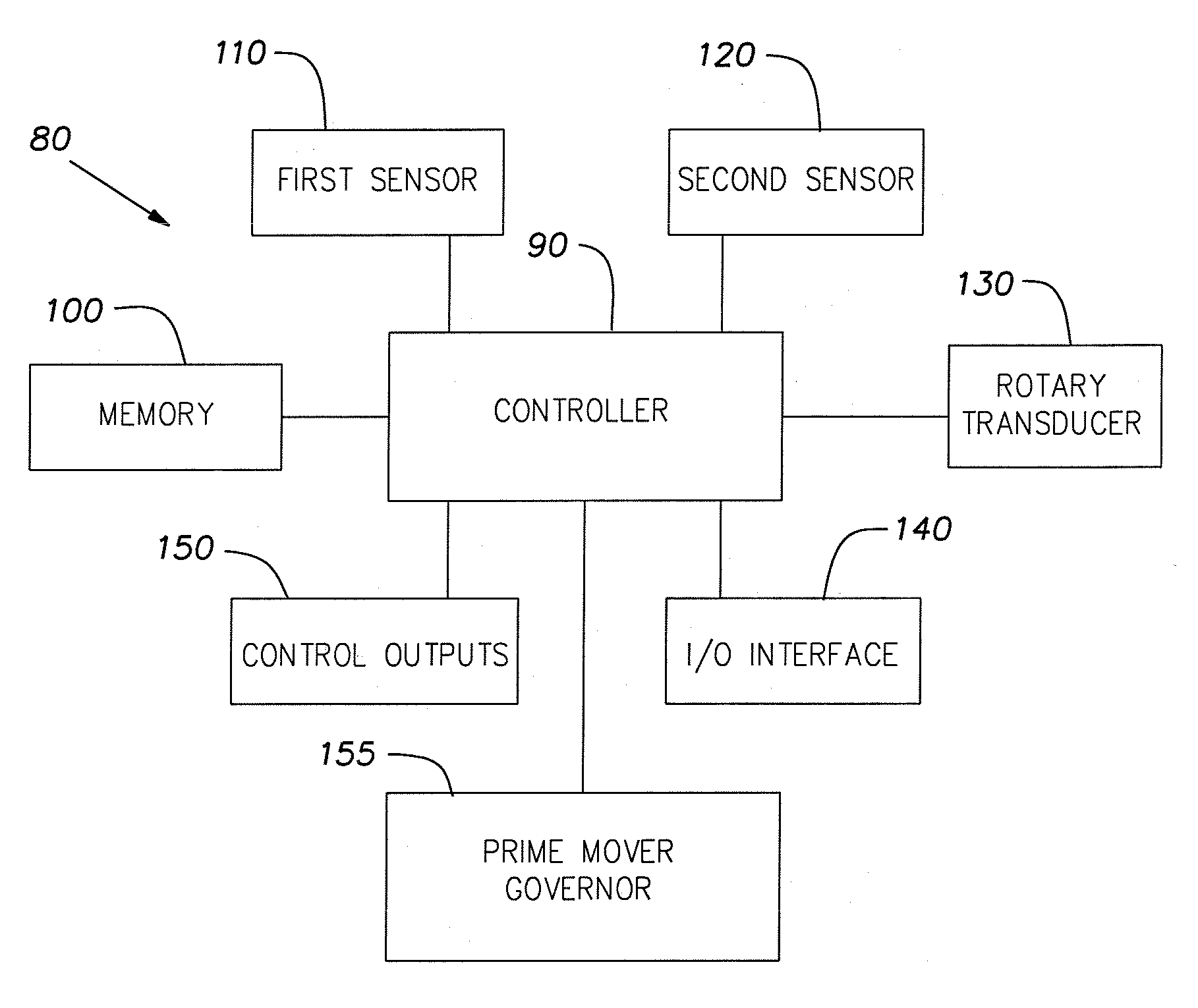
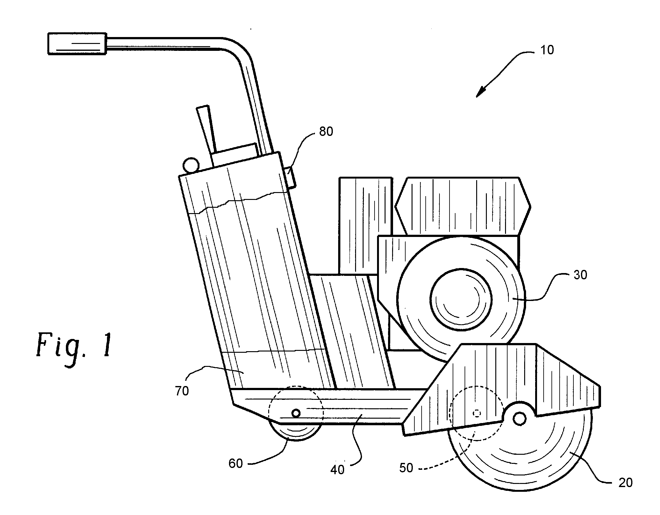
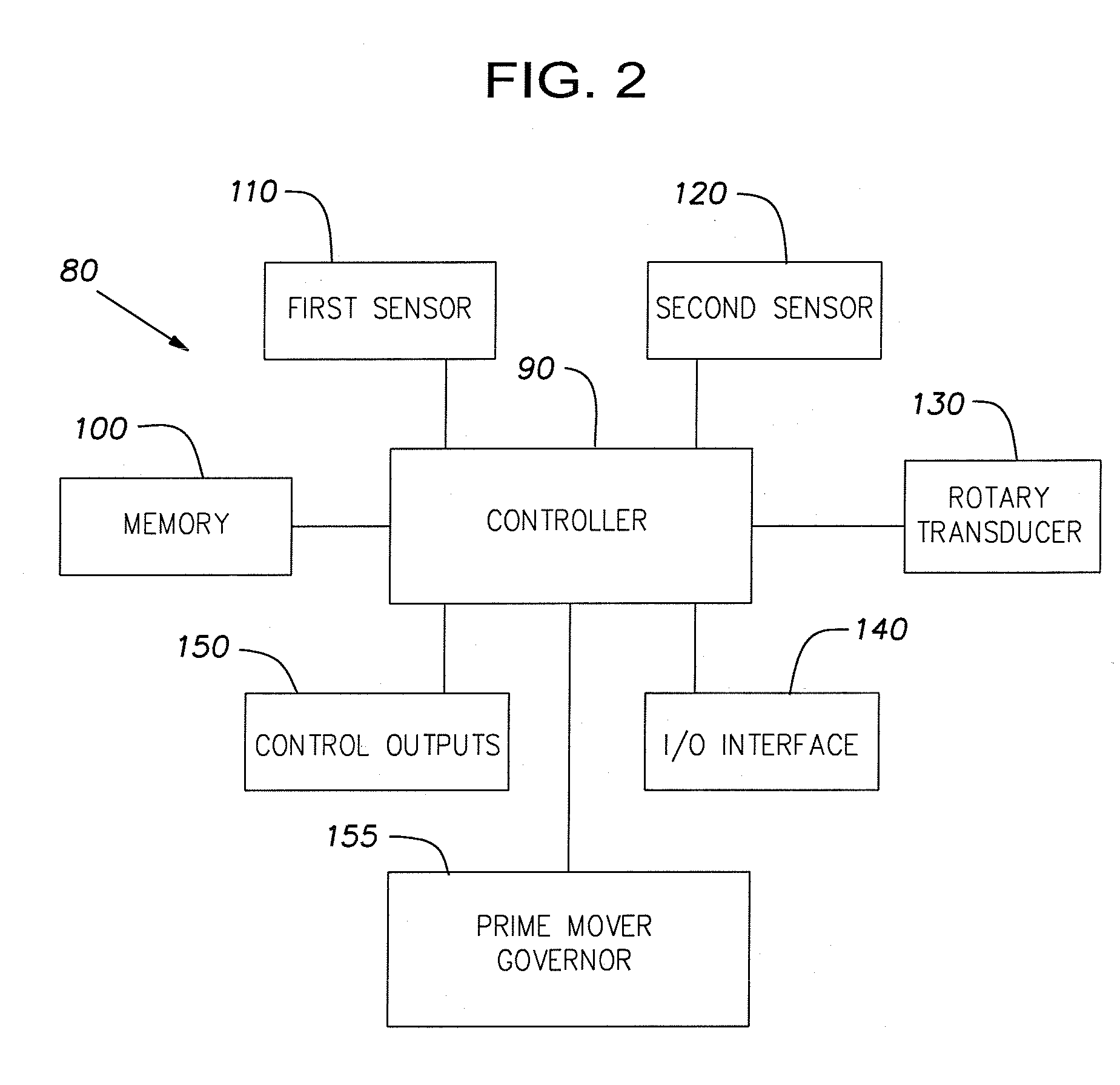
[0014] With reference to FIG. 1, a self-propelled concrete saw 10 comprises a diamond impregnated saw blade 20, a power plant (illustrated as an internal combustion engine) 30 and an associated drive system for providing rotational energy to the saw blade 20, a frame 40 for supporting the power plant 30, and a set of front wheels 50 and rear wheels 60 connected to the frame. In the schematically illustrated self-propelled concrete saw 10, the rear wheels 60 are driven in a conventional manner using a prime mover 70, typically a hydraulic drive system such as that shown in U.S. Pat. No. 5,810,448 which is incorporated herein by reference in its entirety. The forward motion speed of the self-propelled concrete saw 10 during a cutting or scoring operation is controlled by a control system 80. It will be appreciated that power plant 30 may comprise any one of a variety of power sources other than an internal combustion motor, such as, for example, a diesel motor or an electric motor.

[0...


PUM

PropertyMeasurementUnit
Speedaaaaaaaaaa
Depthaaaaaaaaaa

Abstract

The present invention provides a forward motion speed control system for a self-propelled concrete saw, a self-propelled concrete saw equipped with a forward motion speed control system and a method of controlling the forward motion speed of a concrete saw during a cutting or scoring operation. In one preferred embodiment of the invention, the forward motion speed control system senses and monitors the speed of a power plant transmitting rotational energy to a saw blade and adjusts the forward motion speed of the self-propelled concrete saw to maximize the forward motion speed of the self-propelled concrete saw while maintaining the speed of the power plant in a peak operational range.

Description

BACKGROUND OF THE INVENTION [0001] 1. Field of Invention [0002] The present invention relates to a saw for cutting concrete, asphalt, and other hard, flat surfaces and, more particularly, to a self-propelled concrete saw equipped with a forward motion speed control system. [0003] 2. Description of Related Art [0004] Large, horizontal slabs of concrete are frequently poured during the construction of buildings, bridges, roads, runways and the like. Once poured, such slabs must often be cut or scored using a concrete saw for various reasons such as, for example, to form expansion joints, to allow for foundation shifting, to create stress cracks along which the slab will split and / or to create high friction surfaces such as for bridge decks and airport runways. In most large-scale applications, a self-propelled concrete saw is used to cut or score the slab. Self-propelled concrete saws are also used to cut or score asphalt, stone and other hard surfaces. [0005] Most self-propelled conc...

Claims


Application Information

Patent Timeline
IPC IPC(8): E01C23/06
CPCB23D59/001E01C23/0933B28D1/045
Inventor MOLLER, KARL H.EDWARDS, BRIAN S.
Owner DIAMOND PROD
Why Eureka
Try Eureka