
Scale-inhibited water reduction in solutions and slurries

a technology of water reduction and solution, applied in the field of scale-inhibited water reduction in solutions and slurries, can solve the problems of difficult finding a permissible site for disposal of such solutions and slurries, difficult to dispose of expensive solutions, and ultimately the problem of disposal or reuse by oil field operators, etc., to enhance improve the efficiency of vaporization, and facilitate reuse.

Inactive Publication Date: 2007-08-23
TOTAL SEPARATION SOLUTIONS
View PDF37 Cites 7 Cited by
  • Summary
  • Abstract
  • Description
  • Claims
  • Application Information

AI Technical Summary

Benefits of technology

"The invention is a system that uses a cavitation device to dewater and reduce the volume of wastep fluid by heating it and removing moisture through the use of bubbles or pockets of partial vacuum. The cavitation device generates thermal energy by implosion of the bubbles, which can be used to operate a steam turbine or engine, or to enhance the efficiency of vaporization. The system can also include a filter to remove solids from the fluid before it enters the cavitation device. The invention can be used in industrial applications such as the oil and gas industry to process fluids and reduce waste."

Problems solved by technology

Whether or not they are diluted, the oil field operator is ultimately faced with the problem of disposal or reuse.
Frequently, finding a permissible site for disposal of such solutions and slurries is difficult and very expensive Disposal is also difficult for other common oil well fluids such as water / oil (or oil / water) emulsions of widely varying composition, including muds.
The cost of trucking to an approved disposal or processing site can be prohibitive in many instances, and accordingly a significant reduction in the volume of such materials is needed in the art.
Conventional methods of dewatering such fluids, such as distillation or simple evaporation, are very susceptible to scale formation on the heat exchange surfaces, which soon renders the distillation or evaporation equipment inoperable.
Conventional methods tend also to be energy inefficient, and do not lend themselves to the use of thermal and electrical energy commonly available at the well site.
Unfortunately the water produced with oil is not fresh water and is typically highly contaminated with both dissolved salts and suspended solids that include very hard to remove oil droplets.
Unfortunately there are some key differences between seawater and produced water.
Unfortunately, water obtained in hydrocarbon production is not a consistent feedstock.
Surface handling of produced water often adds oxygen that oxidizes the components of the produced water.
Changes in temperature and pressure cause significant scale deposition.
Not only does the produced water volume from a well typically increase with time, there are upsets that change everything.
Given the variability of the produced oilfield water it has been very difficult to design the pretreatment system particularly for reverse osmosis membranes.
To evaporate produced water there are some major issues.
Downhole disposal is an environmentally acceptable alternative to evaporation and it is one of the least expensive alternatives; however, it often requires trucking or piping that adds considerable cost.
The other major problem is scale.
Scale is detrimental to an evaporation process that uses heat.
First there is loss of efficiency. as the scale starts to insulate the hot heat exchanger surface from the fluid.
Unfortunately, corrosion must also be considered.
Unfortunately oilfield waters typically contain an order of magnitude greater concentration of hardness.
Furthermore the hardness can vary from a relatively benign calcium carbonate compound to a nuisance calcium sulfate, but there is also hazardous barium sulfate scale and even radioactive strontium sulfate scaling.
Unfortunately it then takes 970.4 BTU per pound of water to vaporize that water into steam.
In doing such work it becomes obvious that this simple design is not efficient.
A conventional steam boiler is not an ideal evaporator of oilfield waters because scale and corrosion rapidly foul the unit and can even cause serious injury.
If you do not need the steam, then it becomes a cost.
It is not only a cost, but often an environmental hazard.
Using a conventional steam boiler is a very inefficient way to evaporate oilfield waters.
That is both costly and not environmentally sound.
It can only provide sensible heat—that is heat the water to the vaporization point.

Method used


Image

  • Scale-inhibited water reduction in solutions and slurries
  • Scale-inhibited water reduction in solutions and slurries
  • Scale-inhibited water reduction in solutions and slurries

Examples


Embodiment Construction

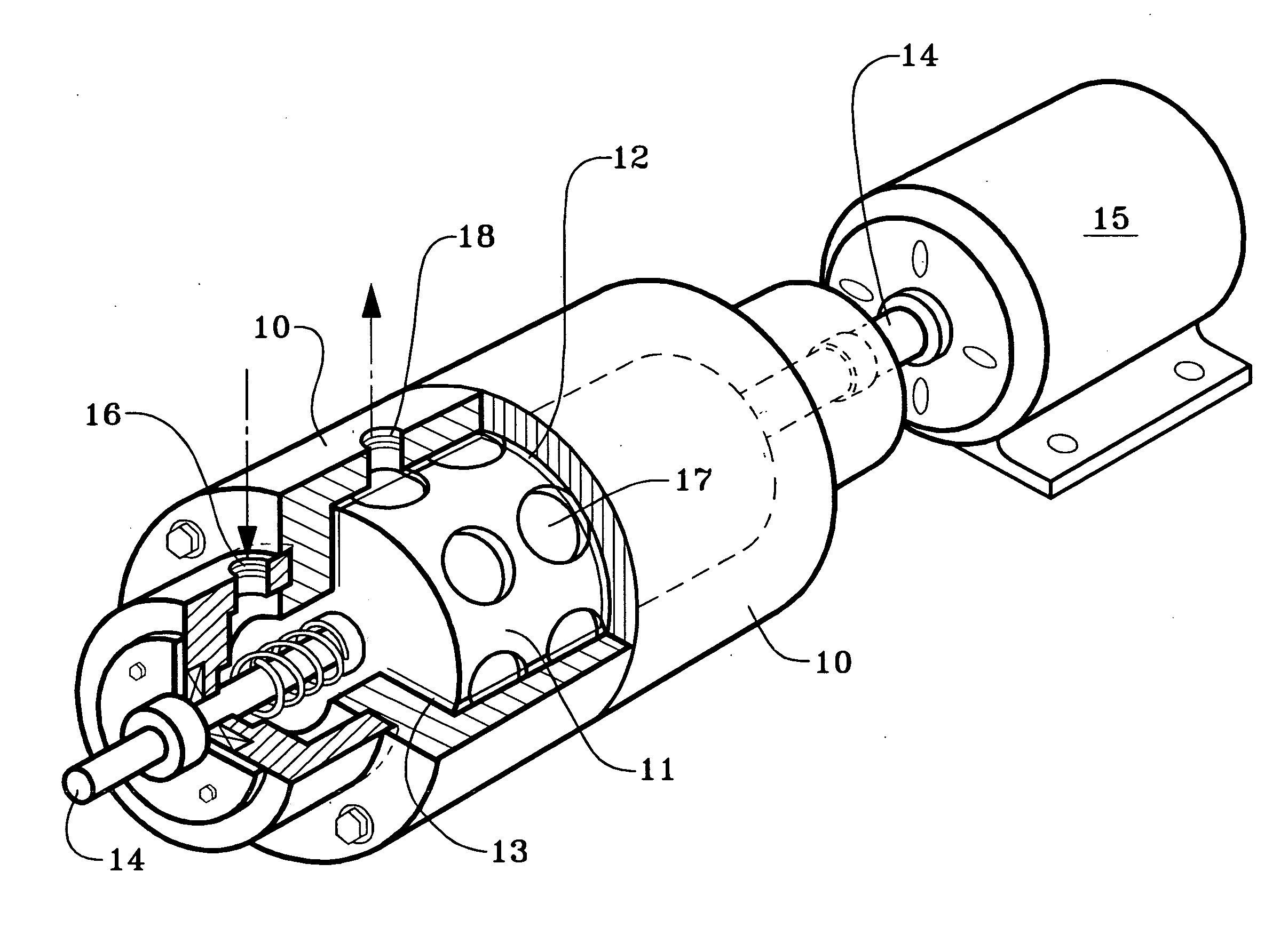
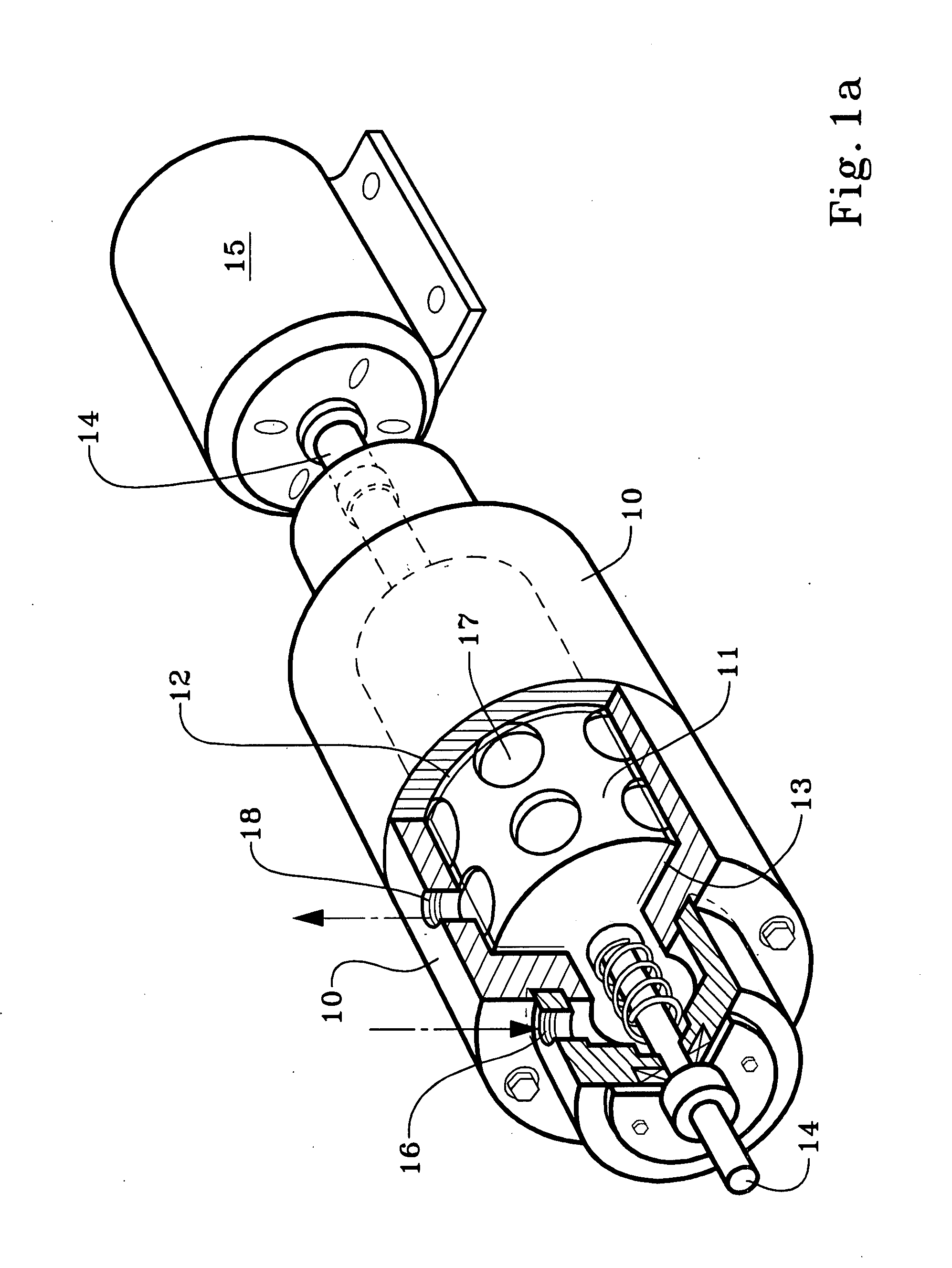
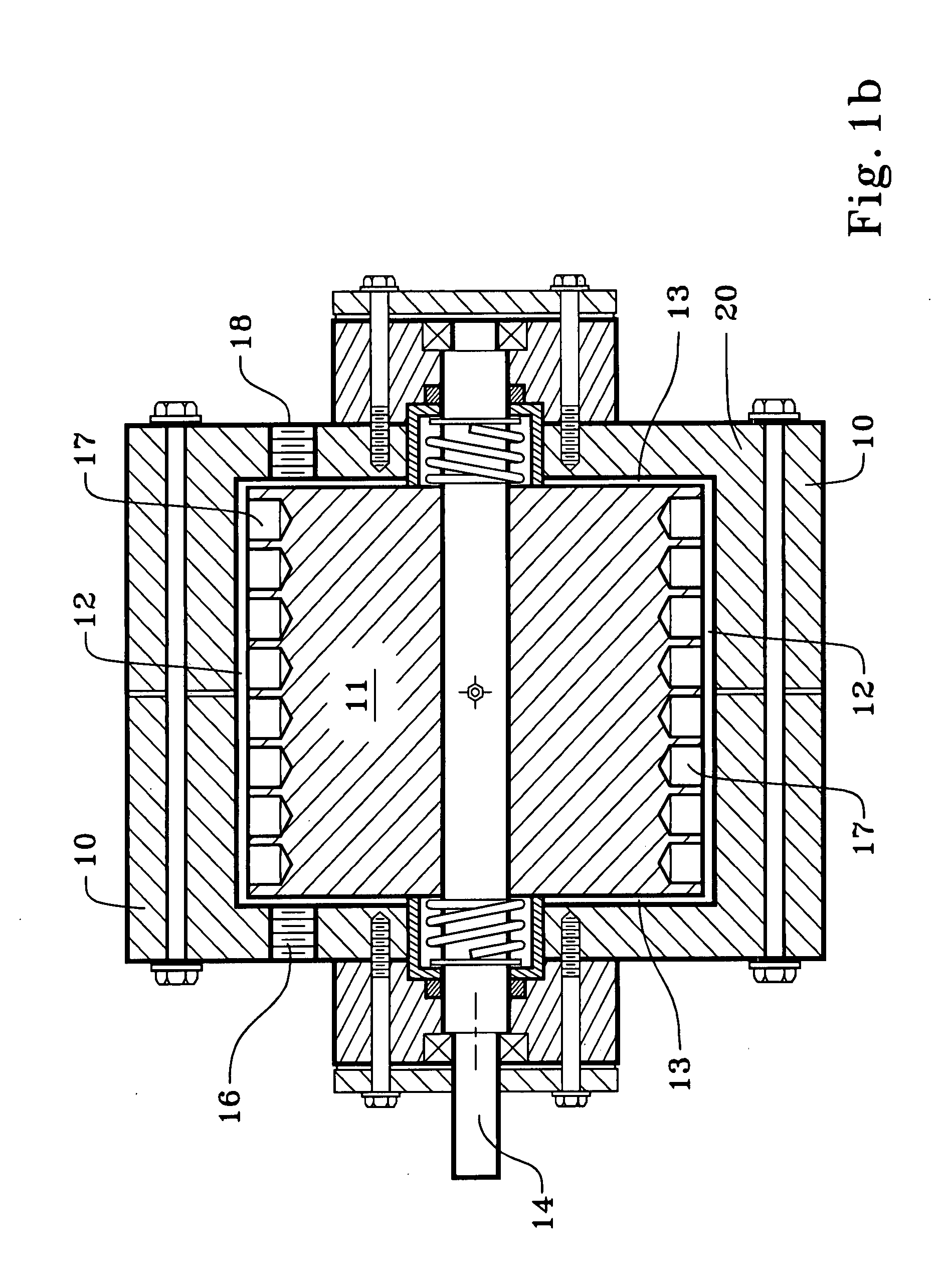
[0032]FIGS. 1a and 1b show two slightly different variations, and views, of the cavitation devices sometimes known as a cavitation pump, or a cavitation regenerator, and sometimes referred to herein as an SPR, which we use in our invention to regenerate solutions comprising heavy brine components.

[0033]FIGS. 1a and 1b are taken from FIGS. 1 and 2 of Griggs U.S. Pat. No. 5,188,090, which is incorporated herein by reference along with related U.S. Pat. Nos. 5,385,298, 5,957,122, and 6,627,784. As explained in the 5,188,090 patent and elsewhere in the referenced patents, liquid is heated in the device without the use of a heat transfer surface, thus avoiding the usual scaling problems common to boilers and distillation apparatus.

[0034] A housing 10 in FIGS. 1a and 1b encloses cylindrical rotor 11 leaving only a small clearance 12 around its curved surface and clearance 13 at the ends. The rotor 11 is mounted on a shaft 14 turned by motor 15. Cavities 17 are drilled or otherwise cut i...


PUM


Abstract

A cavitation device is used to reduce the water content of used or wastep solutions and slurries, including oil well fluids and muds, solution mining fluids, industrial oil / water emulsions, and other used or wastep aqueous industrial fluids. A main reason for reducing the water content of such fluids is to facilitate their disposal or reuse. Thermal energy from the steam and vapor produced by the non-scaling cavitation device is recycled in steam turbines or piston expander engines, or otherwise facilitates evaporation through a membrane or condensation to useful fresh water; the efficiency of the process can be enhanced by mechanical vapor recompression.

Description

RELATED APPLICATION [0001] This application claims the full benefit of copending application Ser. No. 11 / 352,889, filed Feb. 13, 2006, which in turn claims the benefit of provisional application 60 / 652,549 filed Feb. 14, 2005 and 60 / 652,711 filed Feb. 14, 2005.TECHNICAL FIELD [0002] A cavitation device is used to reduce the water content of used or wastep solutions and slurries, including oil well fluids and muds, solution mining fluids, industrial oil / water emulsions, and other used or wastep aqueous industrial fluids. A main reason for reducing the water content of such fluids is to facilitate their disposal or reuse. Thermal energy from the steam and vapor produced by the non-scaling cavitation device is recycled in steam turbines or piston expander engines, or otherwise facilitates evaporation or condensation to useful fresh water. BACKGROUND OF THE INVENTION [0003] In oil and other hydrocarbon production, drilling, completion and workover, fluids are typically circulated down t...

Claims


Application Information

Patent Timeline
Patent Type & Authority Applications(United States)
IPC IPC(8): E21B47/00
CPCE21B21/063
Inventor SMITH, KEVIN W.SLOAN, ROBERT L.SMITH, HARRY D. JR.
Owner TOTAL SEPARATION SOLUTIONS
Learn More