
Heat exchanger

a heat exchanger and heat exchanger technology, applied in the field of heat exchangers, can solve the problems of increasing manufacturing costs, and achieve the effect of reducing the steps of manufacturing the heat exchanger

Inactive Publication Date: 2007-08-23
DENSO CORP
View PDF11 Cites 45 Cited by
  • Summary
  • Abstract
  • Description
  • Claims
  • Application Information

AI Technical Summary

Benefits of technology

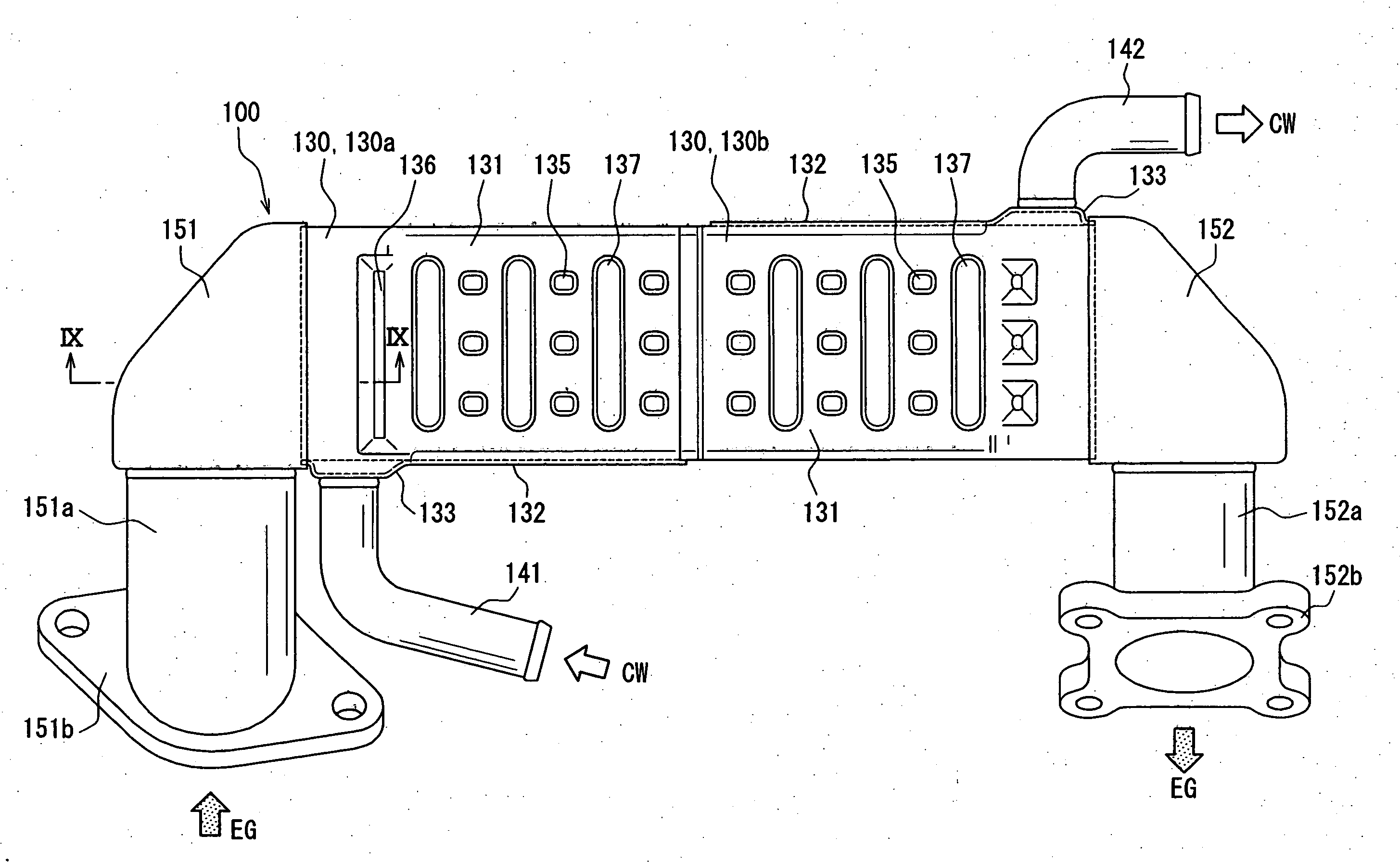
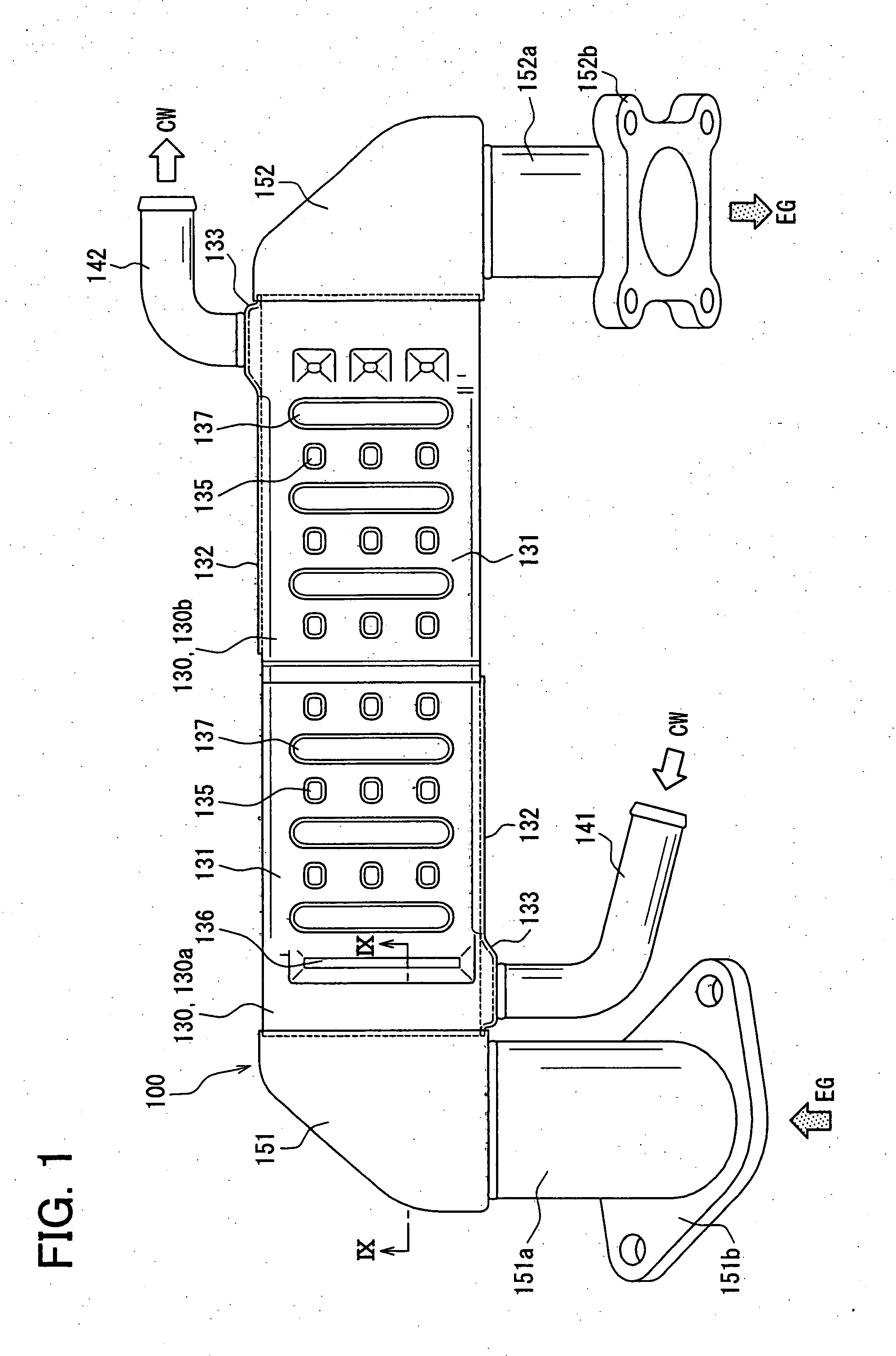
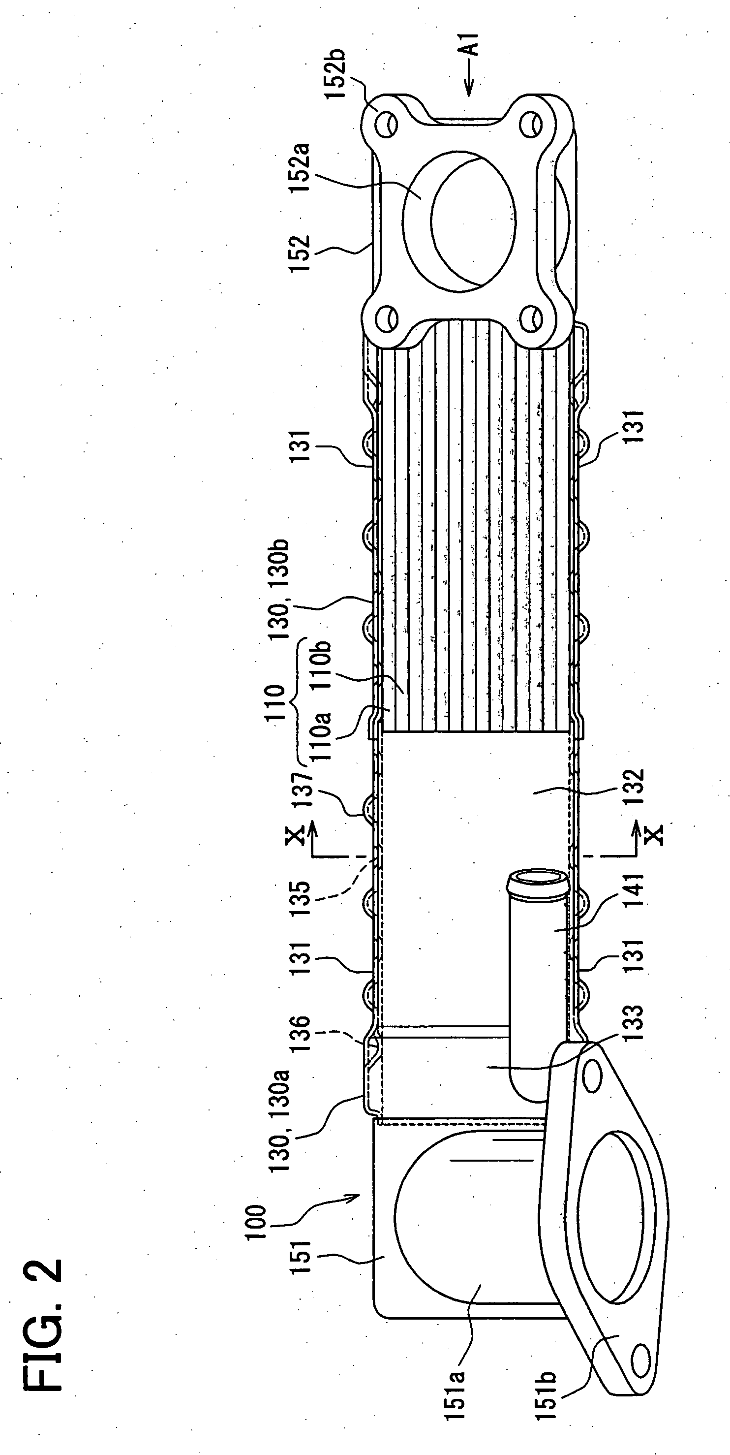
[0009]In this construction, the spaces for the second fluid passages are provided between the adjacent tubes by the projections, without using core plates. Therefore, steps of manufacturing the heat exchanger reduces.

Problems solved by technology

Thus, steps increase in the manufacturing process, resulting in increase in manufacturing costs.

Method used


Image

  • Heat exchanger
  • Heat exchanger
  • Heat exchanger

Examples


second embodiment

[0081]A second embodiment will be described with reference to FIG. 13. In the second embodiment, a EGR gas cooler 100A has bypass tubes 110A and a partition wall 160 in addition to the structure of the EGR gas cooler 100 of the first embodiment. In FIG. 13, the water inlet part is exemplary shown because a water inlet part and a water outlet part have the similar structure.

[0082]The bypass tubes 110A are stacked on one side (lower side in FIG. 13) of the stack of the tubes 110. The bypass tubes 110A define the gas passages 114 through which the exhaust gas flows, similar to the tubes 110. The partition wall 160 is interposed between the tube 110 and the bypass tube 110A. The partition wall 160 is for example made of stainless and has a rectangular shape. The stack of the tubes 110, partition wall 160 and bypass tubes 110A is disposed in the water tank 130.

[0083]Similar to the first embodiment, the water tank 130 includes the first tank member 130a and the second tank member 130b. Th...


PUM


Abstract

A heat exchanger has tubes defining first fluid passages through which a first fluid flows therein, an inlet part and an outlet part. Each tube has a first main wall and a second main wall. At least one of the first main wall and the second main wall has a projection projecting outside of the tube along a peripheral end and a first recess and a second recess recessed from the projection. The tubes are stacked such that the first and second main walls are opposed to each other and spaces are provided between the adjacent tubes by the projections. The spaces define second fluid passages through which a second fluid flows. The inlet part is in communication with the second fluid passages through the first recesses and the outlet part is in communication with the second fluid passages through the second recesses.

Description

CROSS REFERENCE TO RELATED APPLICATION[0001]This application is based on Japanese Patent Application No. 2006-27277 filed on Feb. 3, 2006 and No. 2007-012991 filed on Jan. 23, 2007, the disclosures of which are incorporated herein by reference.FIELD OF THE INVENTION[0002]The present invention relates to a heat exchanger, which is for example used in an exhaust gas recirculation system (EGR) for performing heat exchange between an exhaust gas and a cooling water.BACKGROUND OF THE INVENTION[0003]Japanese Unexamined Patent Publication No. 2003-106790 (U.S. Pat. No. 6,595,274 B2) discloses an exhaust gas heat exchanger, which is for example used in an exhaust gas recirculation system. The exhaust gas heat exchanger performs heat exchange between a part of an exhaust gas that is discharged from an engine and returned to an air intake side of the engine and a cooling water, thereby to cool the exhaust gas.[0004]In the exhaust gas heat exchanger, stacked tubes are housed in a tank, and bon...

Claims


Application Information

Patent Timeline
Patent Type & Authority Applications(United States)
IPC IPC(8): F28D7/02
CPCF02M25/0728F02M25/0737F28D7/1684Y02T10/121F28D21/0003F28F1/40F28F3/042F28D9/0031F02M26/25F02M26/32
Inventor OOFUNE, YUUHAYASHI, TAKAYUKI
Owner DENSO CORP
Learn More