
Hydraulic braking system that provides acceleration assistance and battery recharging

Inactive Publication Date: 2007-08-09
DUCHARME LEONARD A
View PDF10 Cites 22 Cited by
  • Summary
  • Abstract
  • Description
  • Claims
  • Application Information

AI Technical Summary

Benefits of technology

[0009] It has been recognized that it would be advantageous to develop a new type of regenerative braking system for light and medium-weight vehicles that would recapture a higher percentage of the vehicle's kinetic energy during the braking process and then use the energy to accelerate the vehicle or, alternatively, to recharge the vehicle's battery pack.
[0010] In accordance with one aspect thereof, the invention provides a magnetic clutch, a continuously variable transmission, a hydraulic pump, a reservoir, a hydraulic accumulator, an electronically controlled valve manifold, a hydraulic motor and an electricity generator. The magnetic clutch is engaged when the vehicle operator indicates that he wants the vehicle to decelerate. The clutch transfers the rotation of the vehicle's wheels to the CVT. The CVT modulates RPM between the wheels and the hydraulic pump, bringing the pump up to maximum RPM gradually, thus preventing the vehicle from slowing too rapidly. As the pump moves hydraulic fluid from the reservoir to the accumulator and pressure begins to build in the accumulator, the pressure requires an increasing amount of energy to rotate the pump, which in turn causes the vehicle's wheels to reduce RPM, eventually, stopping the vehicle. Note that as the wheels begin to slow, the CVT continues to adjust gearing ratio so as to keep the pump operating at or near peak capacity as long as possible. When pressure in the accumulator reaches a sufficiently high level, a gate valve is opened, allowing the pressurized fluid to flow through a hydraulic motor, which turns a generator. The electricity created by the generator is used to replenish the vehicle's battery pack. Because pressure to the motor can be carefully regulated, electricity can be generated at the exact amperage necessary for optimal charging of the battery. Alternatively, the pressure from the accumulator could be routed back through the pumps, which would then become motors. Under this scenario, the pressure would be used to accelerate the vehicle.

Problems solved by technology

In conventional vehicles, this kinetic energy is lost during the braking process: friction is applied via brake pads and rotors causing the vehicle to slow.
Given the relative, escalating cost of energy, wasting a vehicle's kinetic energy is no longer practical.
However, these types of systems fail to utilize much of the kinetic energy, primarily because battery storage systems frequently used in electric and hybrid vehicles can't store the amperage at the rate at which it is generated.
However, the vehicle's battery may not be able to take more than, say, 50 amps as a recharging current.
Consequently, much of the amperage generated during the braking process is lost.
However, the Ford system is simplistic in design and does not lend itself to smaller applications, such as compact-to-midsize electric and hybrid commuter vehicles.
As the pump moves hydraulic fluid from the reservoir to the accumulator and pressure begins to build in the accumulator, the pressure requires an increasing amount of energy to rotate the pump, which in turn causes the vehicle's wheels to reduce RPM, eventually, stopping the vehicle.

Method used


Image

  • Hydraulic braking system that provides acceleration assistance and battery recharging
  • Hydraulic braking system that provides acceleration assistance and battery recharging
  • Hydraulic braking system that provides acceleration assistance and battery recharging

Examples


Embodiment Construction

[0019] Reference will now be made to the exemplary embodiments illustrated in the drawings, and specific language will be used herein to describe the same. It will nevertheless be understood that no limitation of the scope of the invention is thereby intended. Alterations and further modifications of the inventive features illustrated herein, and additional applications of the principles of the inventions as illustrated herein, which would occur to one skilled in the relevant art and having possession of this disclosure, are to be considered within the scope of the invention.

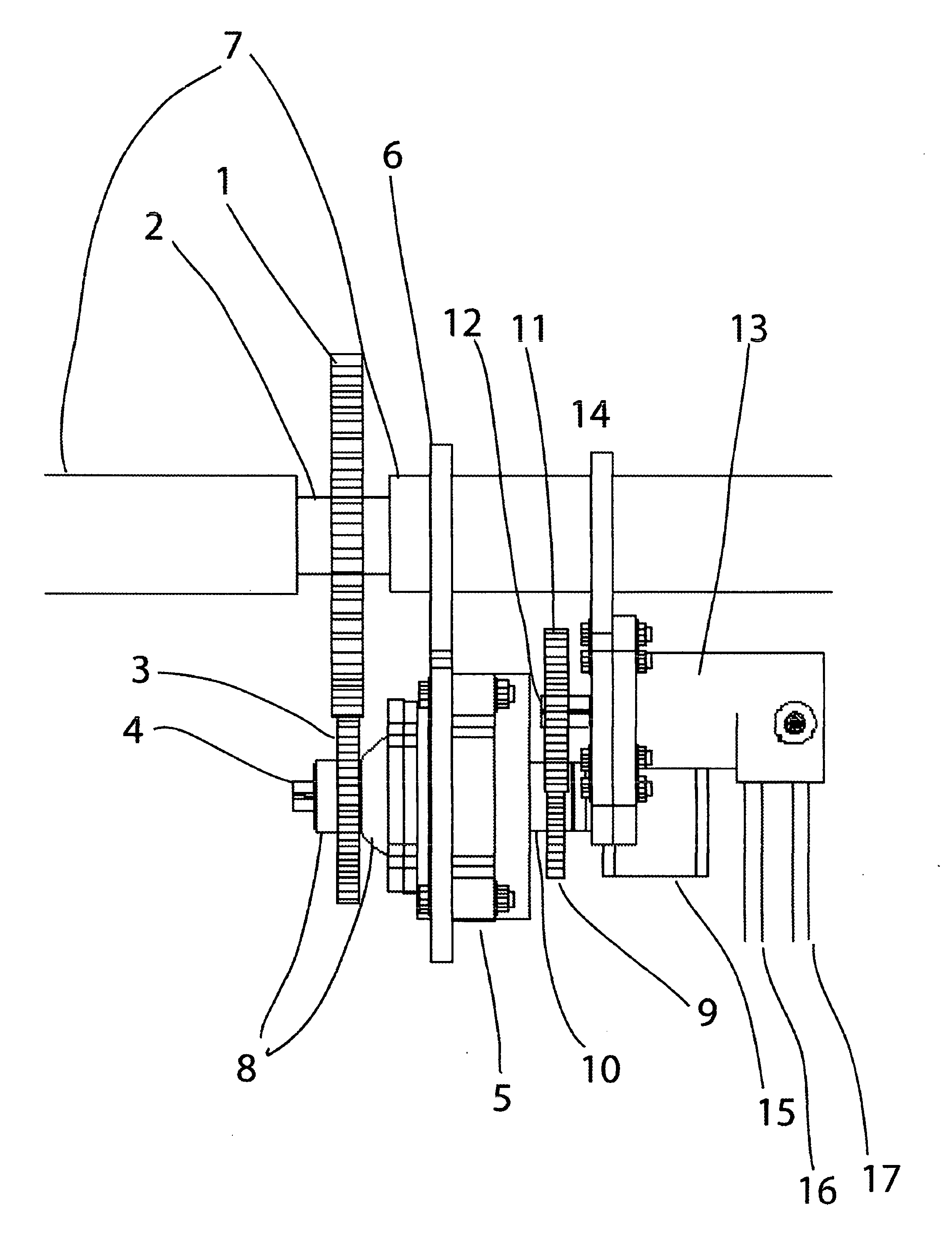
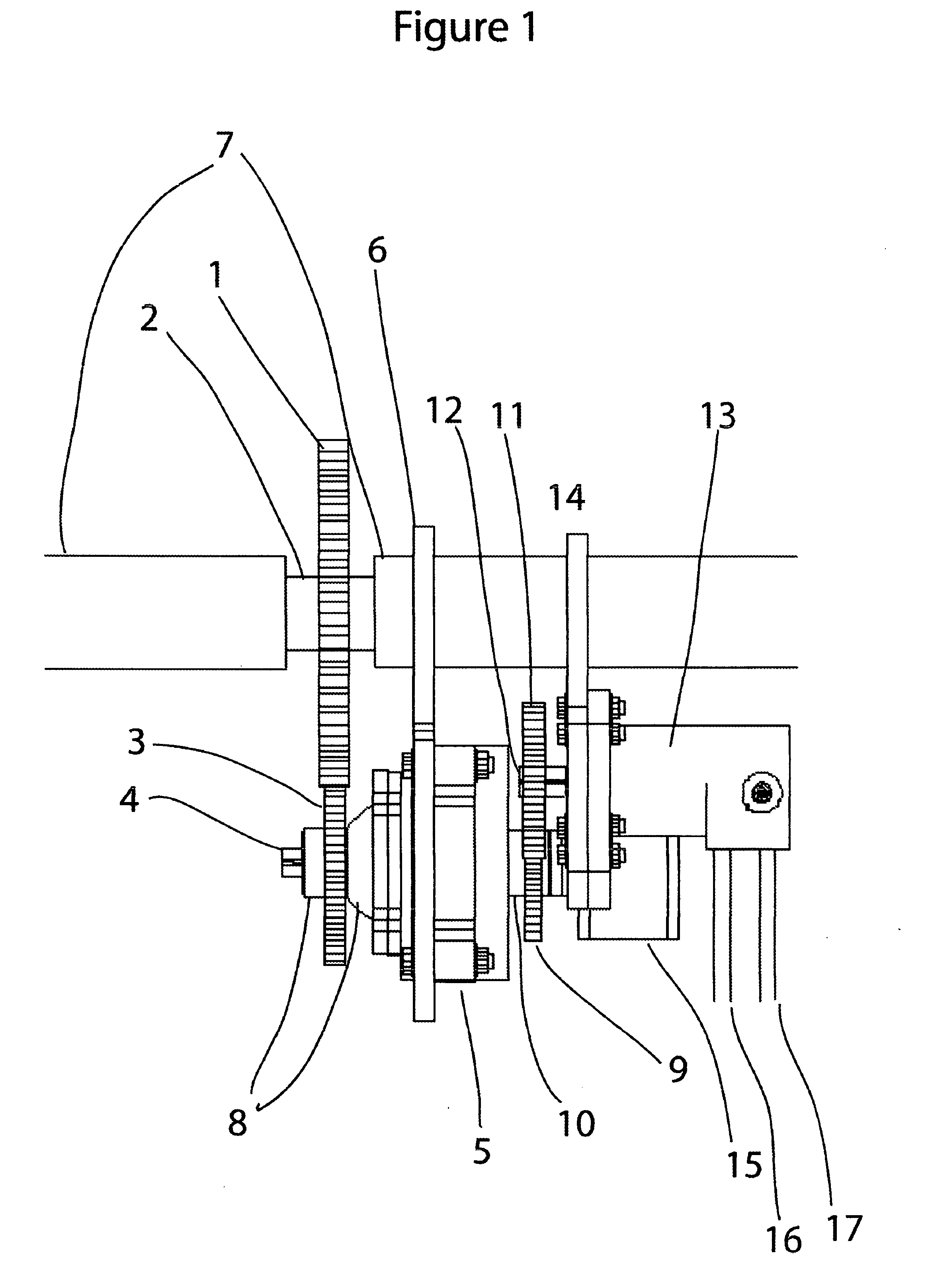
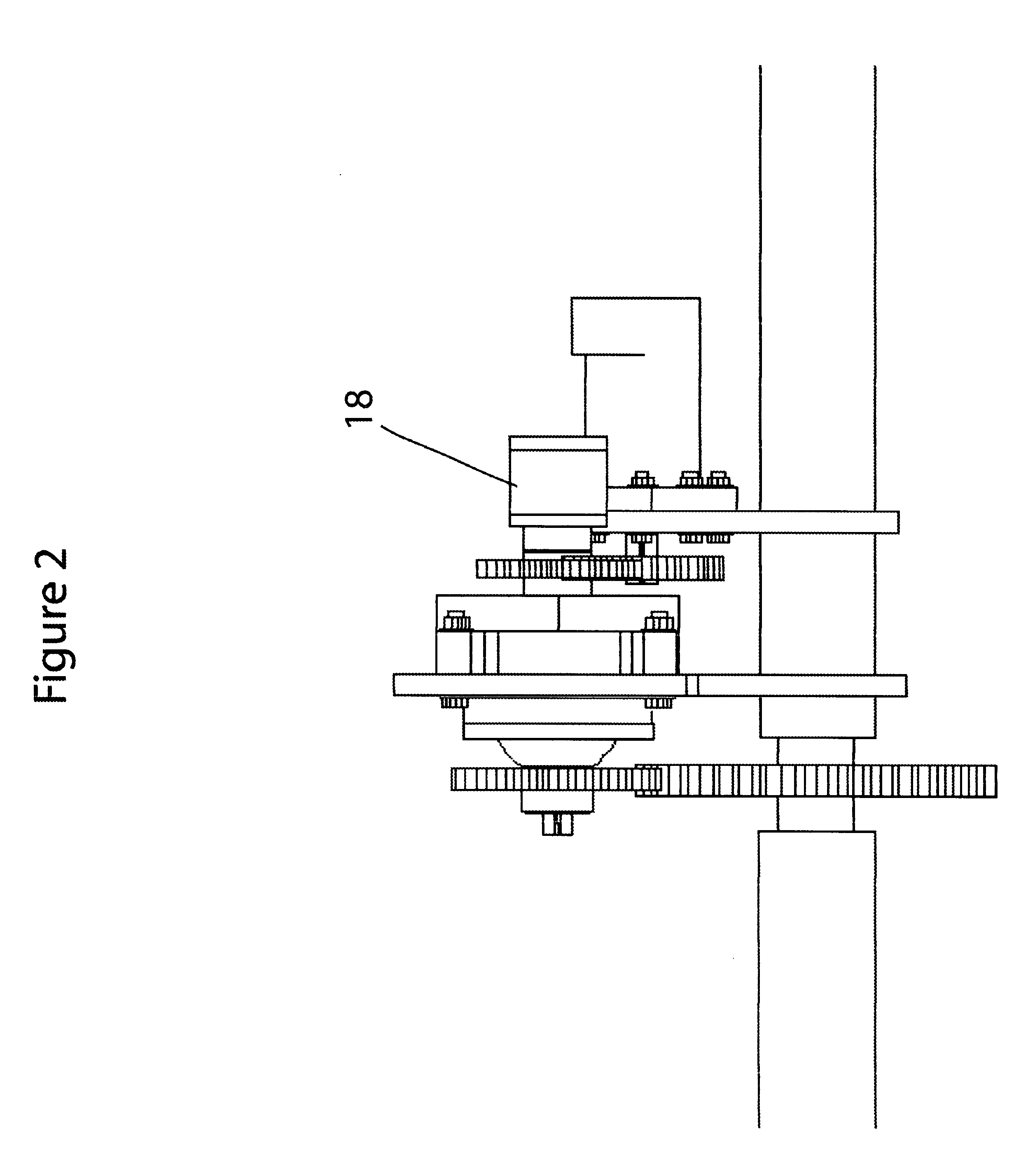
[0020] The invention advantageously utilizes hydraulic devices in combination with a transmission and generator to create a novel regenerative braking system which captures the vehicle's kinetic energy during the braking process and utilizes it to recharge the vehicle's battery or, alternatively to accelerate the vehicle. [0021]FIG. 1 shows a top down view of the pumping assembly of the invention. A gear 1 is s...


PUM


Abstract

The invention is a hydraulic braking system that captures an electric / hybrid vehicle's kinetic energy and utilizes it to assist in accelerating the vehicle or to recharge the vehicle's battery pack.

Description

PRIORITY CLAIM [0001] The present application claims the benefit of U.S. Provisional patent application Ser. No. 60 / 748,934, filed Dec. 12, 2005, and entitled HYDRAULIC REGENERATIVE BRAKING SYSTEM THAT PROVIDES ACCELERATION ASSISTANCE AND BATTERY RECHARGING.BACKGROUND [0002] 1. Field of the Invention [0003] The present invention relates generally to hydraulic braking systems for vehicles. More particularly, the present invention relates to a design for a hydraulic braking system that captures an electric / hybrid vehicle's kinetic energy during the braking process, stores the energy as pressure in an hydraulic accumulator(s), and utilizes the pressure to drive an electric generator, which in turn, recharges the vehicle's battery pack, or, alternatively, uses the stored energy to assist in the acceleration of the vehicle. [0004] The purpose of the invention is to provide a braking system that will capture a vehicle's kinetic energy during the braking process, rather than expend it as h...

Claims


Application Information

Patent Timeline
IPC IPC(8): B60T8/64
CPCB60K7/0015B60K17/043B60T1/093B60K2007/0061B60L2220/46B60K2007/0038
Inventor DUCHARME, LEONARD A.
Owner DUCHARME LEONARD A
Learn More