Wire bonding method and apparatus

a wire bonding and wire bonding technology, applied in the field of wire bonding apparatus, can solve the problems of lowering the unit per hour (uph) achievable by unable to perform wire bonding, and unable to meet the requirements of the whole wire bonding process, and achieve the effect of high bonding accuracy

Inactive Publication Date: 2007-08-09
ASM ASSEMBLY AUTOMATION LTD
View PDF9 Cites 4 Cited by
  • Summary
  • Abstract
  • Description
  • Claims
  • Application Information

AI Technical Summary

Benefits of technology

[0012] It is thus an object of the invention to seek to provide a wire bonding method and apparatus to avoid at least some of the disadvantages of the aforesaid prior art to achieve higher bonding accuracy while being able to perform PR processing and wire bonding substantially concurrently.

Problems solved by technology

In such cases, wire bonding cannot be performed while PR processing has yet to be completed.
As a result, there is a bottleneck created during the duration of PR processing and the units per hour (UPH) achievable by the whole wire bonding process is lowered.
However, implementing multiple rotary work-holders with theta-tables and theta motors for concurrent PR processing and wire bonding operations have several problems.
One problem is that the effective bonding area is limited due to the limited accuracy of theta motors.
This introduces further errors when determining the precise locations of the bonding points.
With a limited bonding area, more frequent loading and unloading of substrates may be necessary, so that idle time for the other processes increases and this adversely affects UPH directly.
Another disadvantage is that hardware correction parameters are necessary for both the theta-table and the cameras for performing PR processing.
The potential for error is magnified.
Worse, it is difficult to enable the two theta motors to rotate identically and if the two theta motors do not rotate to identical target angles, this leads to higher PR alignment failure rates and lower UPH.
When using theta-tables, due to limited accuracy, variation of placement of the LED devices may lead to failure in PR alignment.
The failure rate is higher when using theta-tables because the discrepancies in the location of the LED between different theta-tables on which substrates are placed are amplified after rotating the work-holders for PR processing and then for bonding.
The further a bonding position is from the center of the theta-table, the higher would be the error.

Method used


Image

  • Wire bonding method and apparatus
  • Wire bonding method and apparatus
  • Wire bonding method and apparatus

Examples


Embodiment Construction

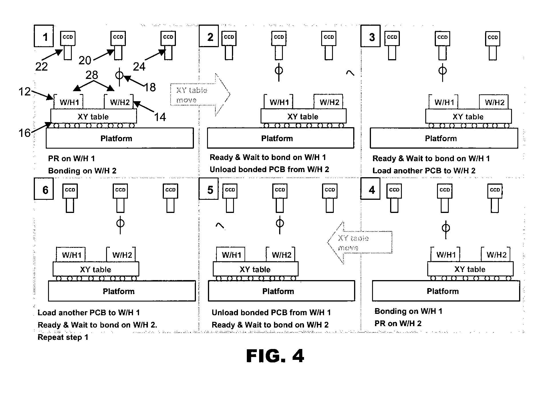
[0021]FIG. 1 is a side view of a wire bonding machine 10 according to the preferred embodiment of the invention. It generally comprises dual carriers, consisting of a left carrier 12 and a right carrier 14, a positioning table such as an XY table for controlling the positions of the dual carriers 12, 14, and a bond head 18 for performing wire bonding. The dual carriers 12, 14 are mounted on the XY table 16.

[0022] There are also a first optical system such as a left-side optical system 22, a second optical system such as a right-side optical system 24, and third optical system such as a central optical system 20. The optical systems 20, 22, 24 preferably have in-built auto-focus capability and adjustable magnification. The central optical system 20 is generally used for viewing bonding points before bonding and for monitoring the quality of bonded wires, whereas the left-side optical system 22 and right-side optical system 24 are arranged and configured to view bonding points on an ...


PUM

PropertyMeasurementUnit
opticalaaaaaaaaaa
timeaaaaaaaaaa
areaaaaaaaaaaa

Abstract

A wire bonding method and apparatus are provided for electronic components to enable PR processing and wire bonding to be carried out substantially concurrently. The apparatus comprises a bond head carrying a bonding tool for performing wire bonding and a rotary motor coupled to the bond head that is configured to change an angular orientation of the bonding tool relative to an electronic component to be bonded. There are first and second carriers for respectively mounting electronic components for wire bonding, and an optical system is arranged and configured to view bonding points on an electronic component mounted on the first carrier when the bonding tool is located over an electronic component mounted on the second carrier to perform wire bonding.

Description

CROSS REFERENCE TO RELATED APPLICATION [0001] This application claims the benefit and priority of U.S. Provisional Application Ser. No. 60 / 759,132 filed on Jan. 13, 2006, and entitled WIRE BONDING METHOD AND APPARATUS, the disclosure of which is incorporated herein by reference.FIELD OF THE INVENTION [0002] The invention relates to wire bonding apparatus, and in particular to wire bonding apparatus that make wire connections between electronic components after wire bonding points have been determined by visual inspection of the electronic components. BACKGROUND AND PRIOR ART [0003] Wire bonding is used in the semiconductor packaging industry to make electrical connections between electronic components, such as a die and a substrate on which the die is attached, or between the die and another die. Such wire bonding apparatus are generally divided into two types: ball bonding apparatus in which a ball is formed at the end of a wire to be bonded, and wedge wire bonding apparatus in whi...

Claims


Application Information

Patent Timeline
Patent Type & Authority Applications(United States)
IPC IPC(8): A47J36/02
CPCB23K20/004B23K20/007H01L24/85H01L2224/78H01L2224/85H01L2924/01033H01L2224/859H01L2924/01075H01L2924/01082H01L24/78H01L2924/00014H01L2924/01059H01L2224/48H01L2224/45099
Inventor HO, WING CHEUNG JAMESLAW, HON SHING EDDIELAM, KAM HONG KENNETH
Owner ASM ASSEMBLY AUTOMATION LTD
Why Eureka
Try Eureka