Bonding fixture for small component

A component and clamping technology, applied in the direction of electrical components, electrical components, etc., can solve the problem of not being able to effectively fix small components, and achieve the effect of improving product quality and yield, improving yield, and improving bonding accuracy

Pending Publication Date: 2019-02-01
GUANGZHOU JINGYOU ELECTRONICS TECH
View PDF0 Cites 0 Cited by
  • Summary
  • Abstract
  • Description
  • Claims
  • Application Information

AI Technical Summary

Problems solved by technology

[0004] In order to overcome the existing technical defects, the present invention provides a bonding fixture for small components, which overcomes the problem that small components cannot be effectively fixed during the bonding process, makes the bonding automatic production process stable and reliable, and improves the bonding accuracy , improve product quality and yield

Method used


Image

  • Bonding fixture for small component
  • Bonding fixture for small component
  • Bonding fixture for small component

Examples


Embodiment 1

[0032] This embodiment aims to provide a bonding fixture for small components, which overcomes the problem that small components cannot be effectively fixed during the bonding process, makes the bonding automatic production process stable and reliable, improves bonding accuracy, and improves product quality and good quality. Rate.

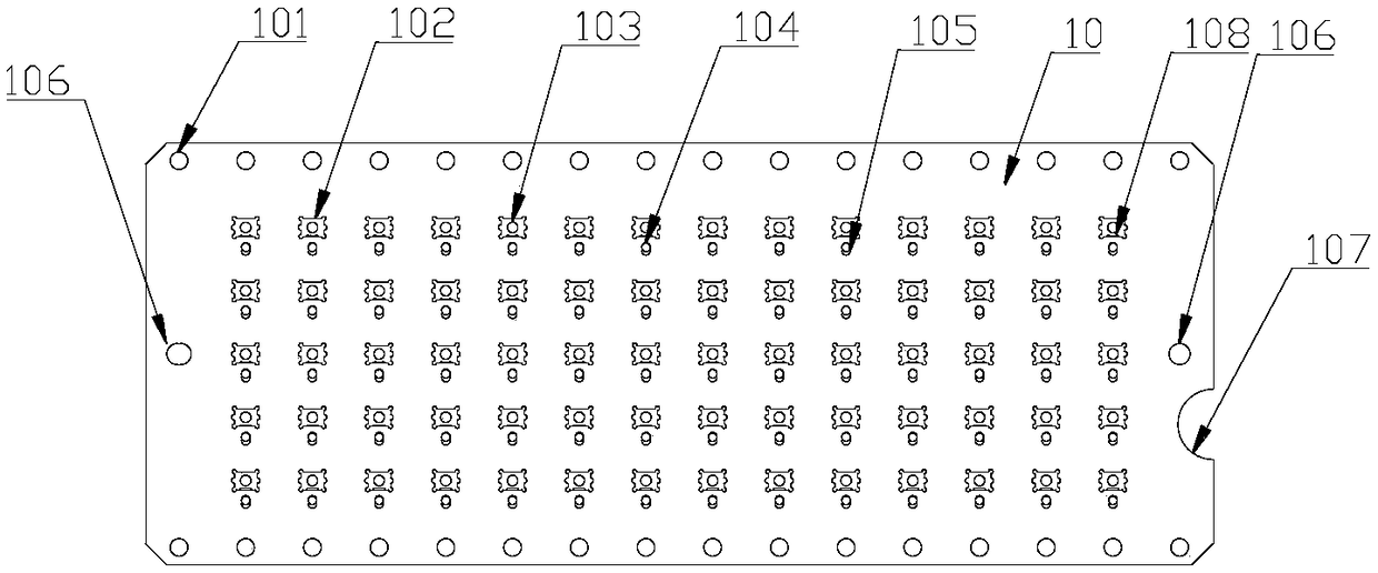
[0033] Such as figure 1 and figure 2 As shown, this embodiment provides a bonding fixture for small components, including a carrier 10 . The slide 10 is roughly square, with chamfered or rounded corners. In order to facilitate automatic production, a set of opposite sides of the slide 10 is provided with openings 101 (etching holes), which are convenient for automatic transmission to ensure stable and reliable transmission. Work slots 102 arranged in an array of 5 rows and 14 columns are arranged on the slide 10 .

[0034] Such as image 3 and Figure 4 As shown, the station groove 102 is roughly square, and its four corners are provided wit...

Embodiment 2

[0040] This embodiment aims to provide a bonding fixture for small components, which overcomes the problem that small components cannot be effectively fixed during the bonding process, makes the bonding automatic production process stable and reliable, improves bonding accuracy, and improves product quality and good quality. Rate.

[0041] This embodiment provides a bonding fixture for small components, including a carrier 10 . The slide 10 is roughly square, with chamfered or rounded corners. In order to facilitate automatic production, a set of opposite sides of the slide 10 is provided with openings 101 (etching holes), which are convenient for automatic transmission to ensure stable and reliable transmission. Work slots 102 arranged in an array of 5 rows and 14 columns are arranged on the slide 10 .

[0042] Station groove 102 is roughly square, and its four corners are provided with circular groove 109, and the depth of circular groove 109 is identical with the depth of...


PUM


Abstract

The invention, which relates to the field of electronic component manufacturing, particularly discloses a bonding fixture for a small component. The bonding fixture comprises a carrying piece; a plurality of station slots are formed in the carrying piece; and at least one elastic mechanism is arranged at the side of each station slot. When components are placed in the station slots, the elastic mechanisms extrude the sides of the components to fix the components in the station slots. With the bonding fixture with a simple structure, fixation of a small device is realized and thus the device isprevented from being offset during the bonding process and is protected from being polluted, so that the quality of the piezoelectric quartz device is improved substantially and the yield of the piezoelectric quartz device is enhanced. Meanwhile, the bonding fixture has advantages of low manufacturing cost, low manufacturing difficulty and low cost, so that the manufacturing cost of the piezoelectric quartz device is lowered.

Description

technical field [0001] The invention relates to the field of manufacturing electronic components, in particular to a bonding fixture for small electronic components. Background technique [0002] Piezoelectric quartz devices and acoustic meter devices are widely used in various wireless communications, instrumentation, automotive electronics, marine engineering, intelligent urban consumption and other fields due to their high stability, such as mobile phones, smart wearables, robots, Bluetooth, navigation, Smart home and other products. [0003] With the upgrading of electronic communication terminals, higher requirements are put forward for piezoelectric quartz devices and SAW devices, especially in terms of stability and miniaturization. At present, the size of chips and wafers of such devices is getting smaller and smaller, most of which are less than 1mm in size at present, and the chips and wafers of these devices need to be connected to the circuit of the base through...

Claims


Application Information

Patent Timeline
Patent Type & Authority Applications(China)
IPC IPC(8): H05K13/04
CPCH05K13/0447
Inventor 欧阳林欧阳晟
Owner GUANGZHOU JINGYOU ELECTRONICS TECH
Why Eureka
Try Eureka