
Settling and evaporation tank apparatus, method and system

a technology of evaporation tank and settling tank, which is applied in the direction of sedimentation settling tank, settling tank heating/cooling, sedimentation settling tank, etc., can solve the problems of significant water contamination by invert mud, dirt, soap or other undesirable substances, disposal or processing of contaminated water, and limited success of evaporation tank, so as to reduce the contaminant level and improve the evaporation rate

Inactive Publication Date: 2007-08-09
R&B OILFIELD RENTALS
View PDF4 Cites 5 Cited by
  • Summary
  • Abstract
  • Description
  • Claims
  • Application Information

AI Technical Summary

Benefits of technology

"The present invention provides a water treatment apparatus, method, and system that can effectively treat contaminated water. The apparatus has a settling region and an evaporation region, with weir means and heat application means to enhance the settling and evaporation of the water. The system also includes a boiler blowdown sub-system for removing contaminants from the evaporation region. The invention has advantages over prior art, such as reducing contaminant build-up and air contamination concerns, and improving evaporation rates."

Problems solved by technology

For example, the oil and gas industry, both in exploration and production, employs numerous processes that result in substantial quantities of water contaminated by invert mud, dirt, soap or other undesirable substances.
Disposal or processing of the contaminated water is a significant problem, and it has spawned a number of attempts to address the situation.
Evaporation tanks have been employed, with some limited success, in treating contaminated water in the oil and gas industry by evaporating the water and leaving a waste residue behind which must be gathered and disposed of.
However, the use of steam coils to cause the evaporation often results in undesirable build-up of contaminant on the coils themselves, resulting in cleaning difficulties The large size required for some evaporation tank designs has made their use cost-prohibitive or presented space allocation issues, and a lack of sufficient insulation in the tank walls has rendered some designs undesirable.
Safety issues are also readily apparent in some proposed tank designs.
Finally, the fact that most of the contaminant remains in the evaporation tank during evaporation means that an air contamination problem can arise when the water level approaches the heating element level.

Method used


Image

  • Settling and evaporation tank apparatus, method and system
  • Settling and evaporation tank apparatus, method and system
  • Settling and evaporation tank apparatus, method and system

Examples


Embodiment Construction

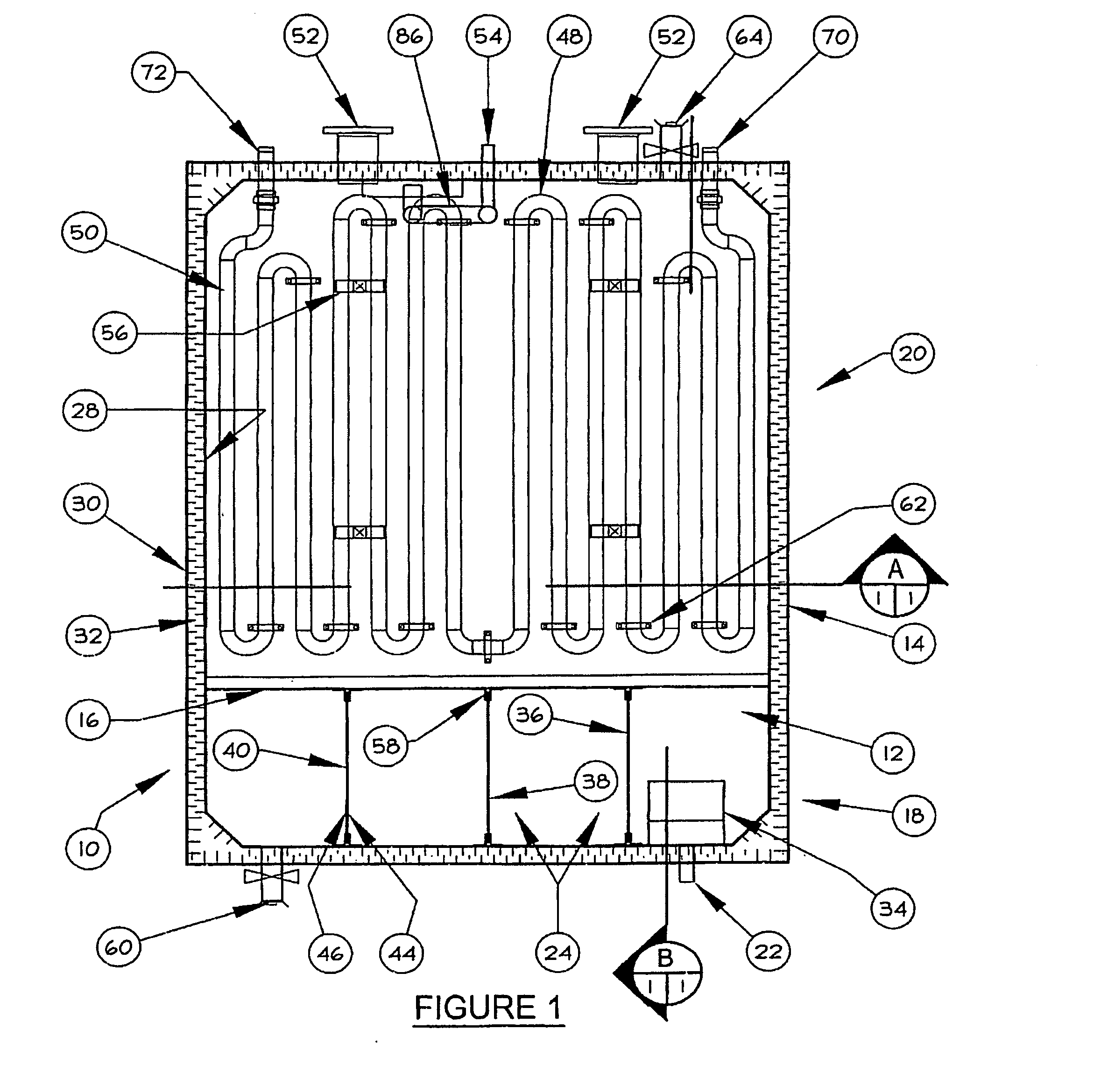
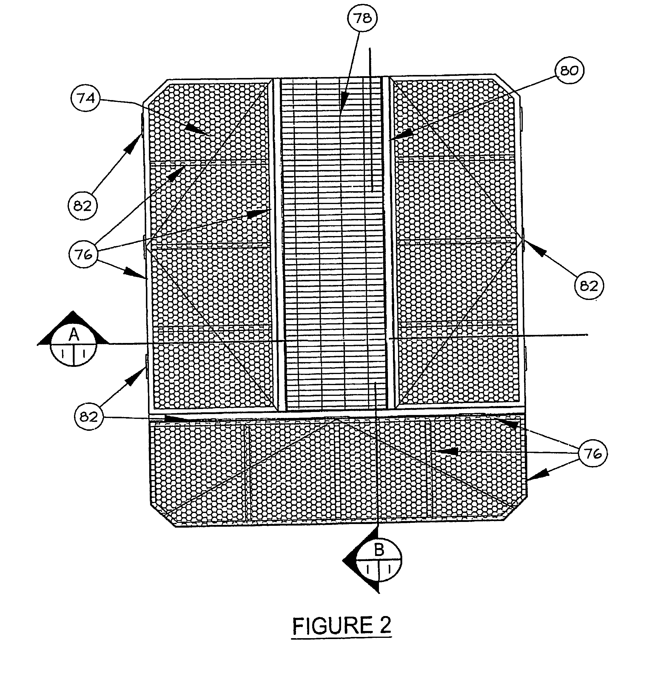
[0046] Referring now in detail to the accompanying drawings, there is illustrated an exemplary embodiment of an apparatus, method and system according to the present invention, the apparatus generally referred to by the numeral 10

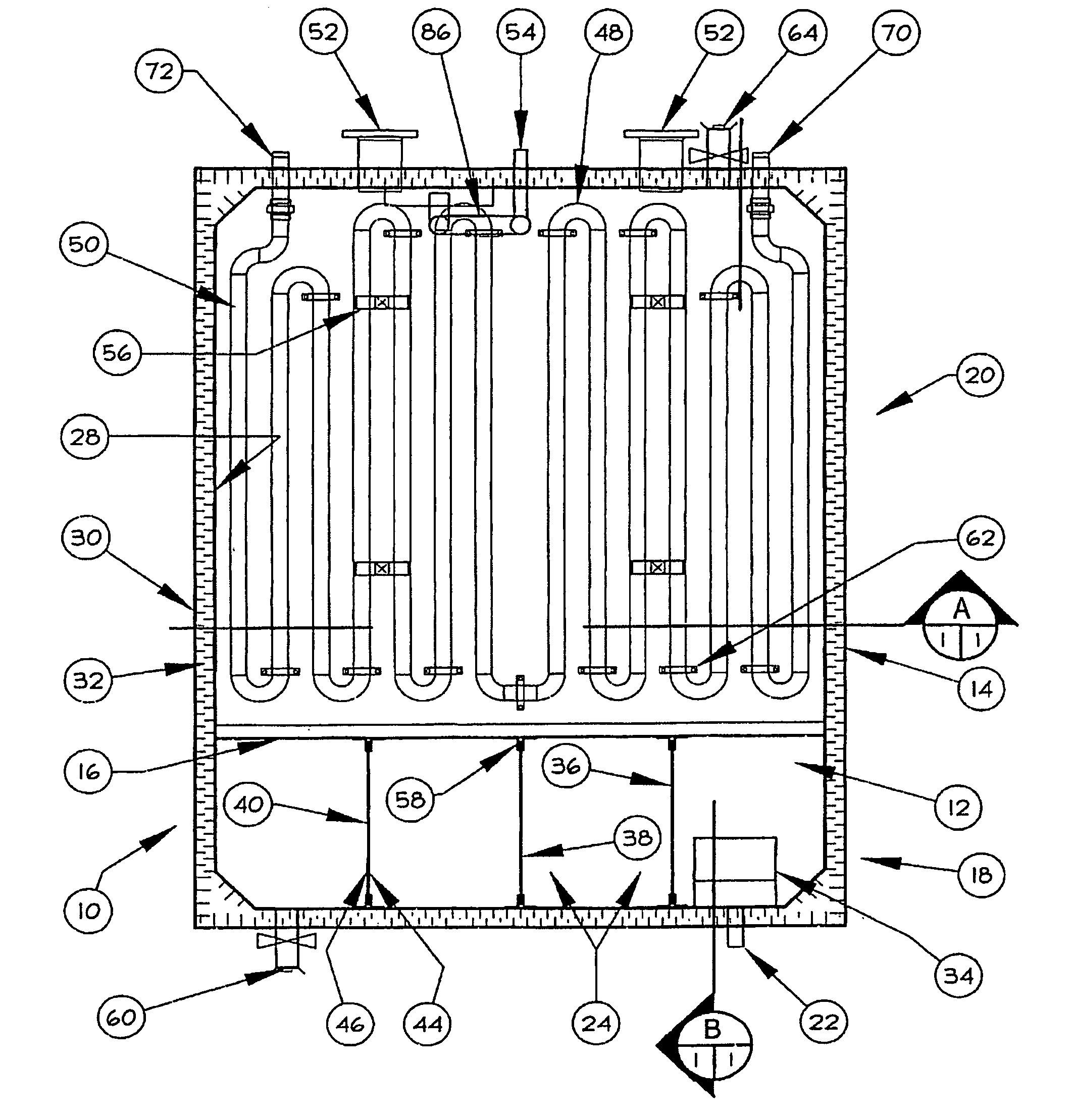
[0047] Referring now to FIG. 1, the water treatment apparatus 10 comprises a base member 12 and a peripheral containment wall 14, each preferably made of plate steel, which collectively contain and help define two distinct regions with distinct functionality with respect to contaminated water treatment, namely a settling region 18 and an evaporation region 20. The plate steel forming the peripheral containment wall 14 is most preferably bent and sheared to enhance structural strength, a feature not known in evaporation tanks currently on the market, and the outer wall 30 is preferably painted a dark color with metallic fragments incorporated to help absorb solar energy. The settling. region 18 and evaporation region 20 are separated by a dividing member 16 ...


PUM


Abstract

An apparatus, method and system for treating contaminated water. The apparatus comprises a tank with a dividing member dividing the tank into a settling region and an evaporation region. The settling region comprises an inlet, weir means, and an outlet, and the evaporation region comprises an inlet and heat application means, the settling region outlet in fluid communication with the evaporation region inlet. The method comprises allowing contaminated water to encounter the weir means, producing contaminants and cleaned water, and transporting the cleaned water to the evaporation region, where the heat application means apply heat to the cleaned water allowing evaporation of the cleaned water. The water treatment system comprises a settling sub-system for receiving contaminated water from a source and allowing contaminants to settle out of the contaminated water, producing cleaned water, and an evaporation sub-system in fluid communication with the settling sub-system for receiving the cleaned water and enabling evaporation of the cleaned water. Preferably, the system further comprises a boiler blowdown sub-system in fluid communication with the evaporation sub-system, wherein an adjacent boiler is allowed to vent boiler contents into the evaporation sub-system during boiler blowdown.

Description

FIELD OF THE INVENTION [0001] The present invention relates to treatment of contaminated water, and more particularly to water treatment through settling and evaporation. BACKGROUND OF THE INVENTION [0002] Many industries generate contaminated water as a by-product of standard processes. For example, the oil and gas industry, both in exploration and production, employs numerous processes that result in substantial quantities of water contaminated by invert mud, dirt, soap or other undesirable substances. Disposal or processing of the contaminated water is a significant problem, and it has spawned a number of attempts to address the situation. [0003] Evaporation tanks have been employed, with some limited success, in treating contaminated water in the oil and gas industry by evaporating the water and leaving a waste residue behind which must be gathered and disposed of. However, the use of steam coils to cause the evaporation often results in undesirable build-up of contaminant on th...

Claims


Application Information

Patent Timeline
Patent Type & Authority Applications(United States)
IPC IPC(8): B01D1/22
CPCB01D1/0017B01D1/06C02F1/048B01D21/009B01D21/02B01D21/003
Inventor PATMORE, RICKY DALE
Owner R&B OILFIELD RENTALS
Learn More