
Heterojunction tunneling field effect transistors, and methods for fabricating the same

a tunneling field and transistor technology, applied in semiconductor devices, diodes, electrical apparatus, etc., can solve the problems of degrading device performance and increasing leakage current, and achieve the effect of enhancing the tunneling current of a tfet devi

Inactive Publication Date: 2007-08-02
IBM CORP
View PDF8 Cites 115 Cited by
  • Summary
  • Abstract
  • Description
  • Claims
  • Application Information

AI Technical Summary

Benefits of technology

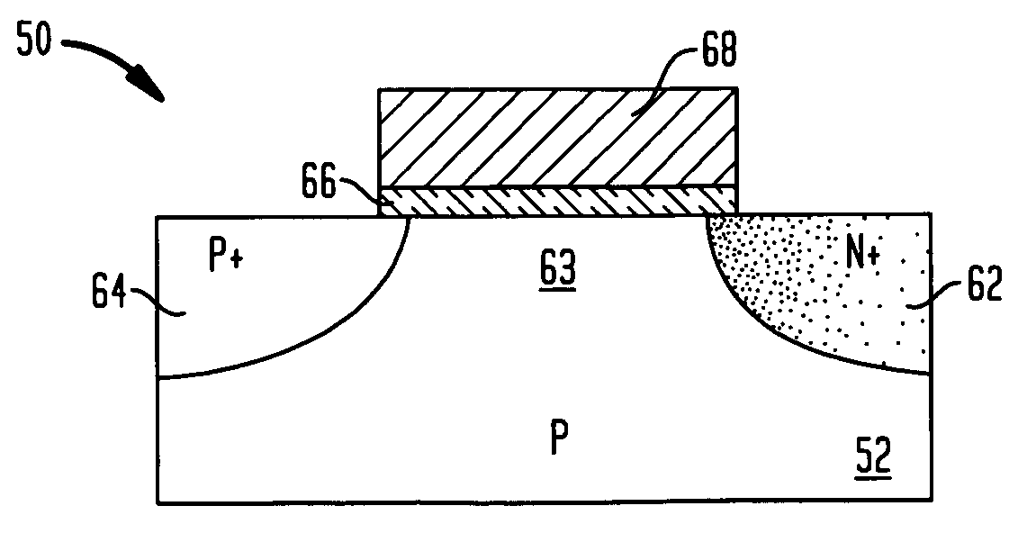
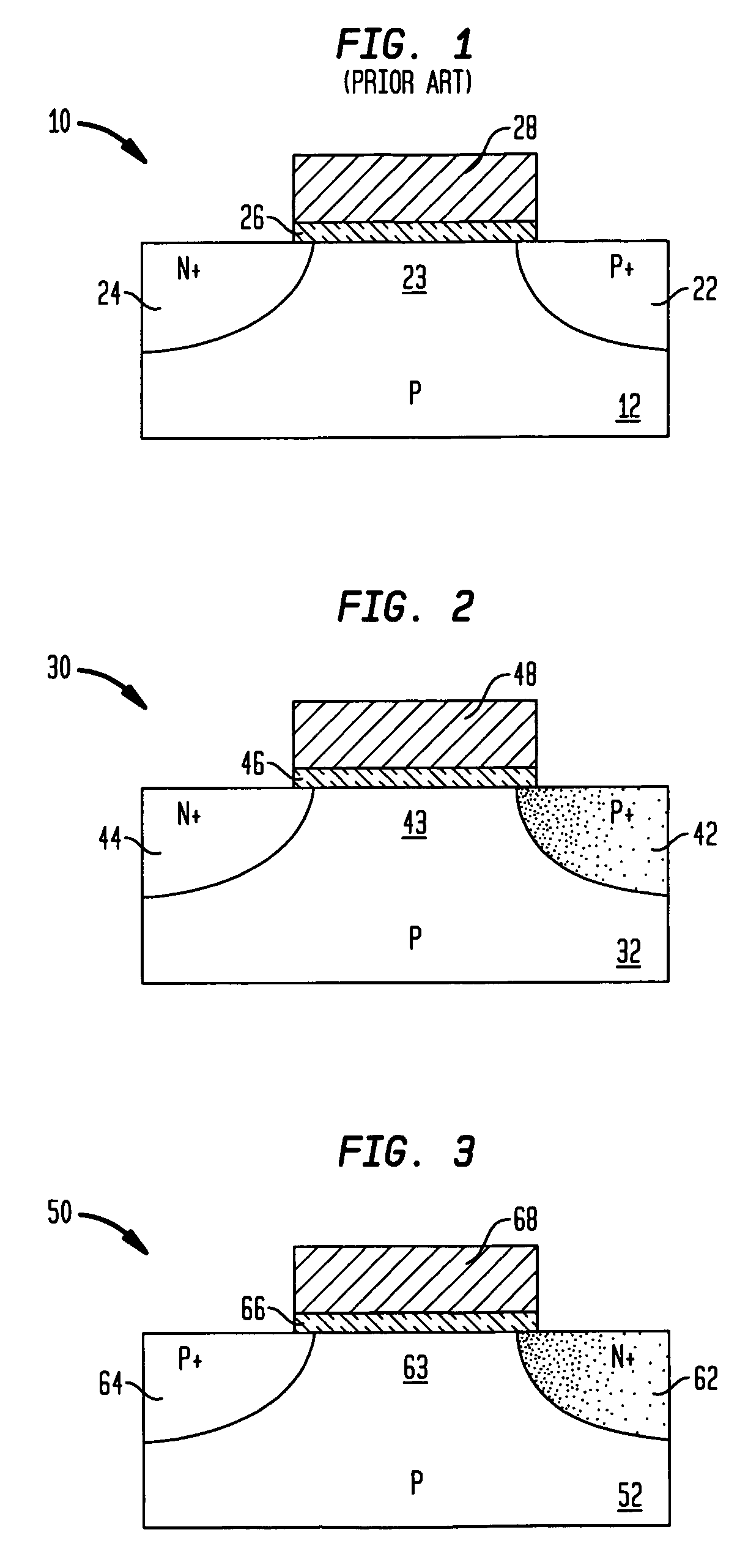
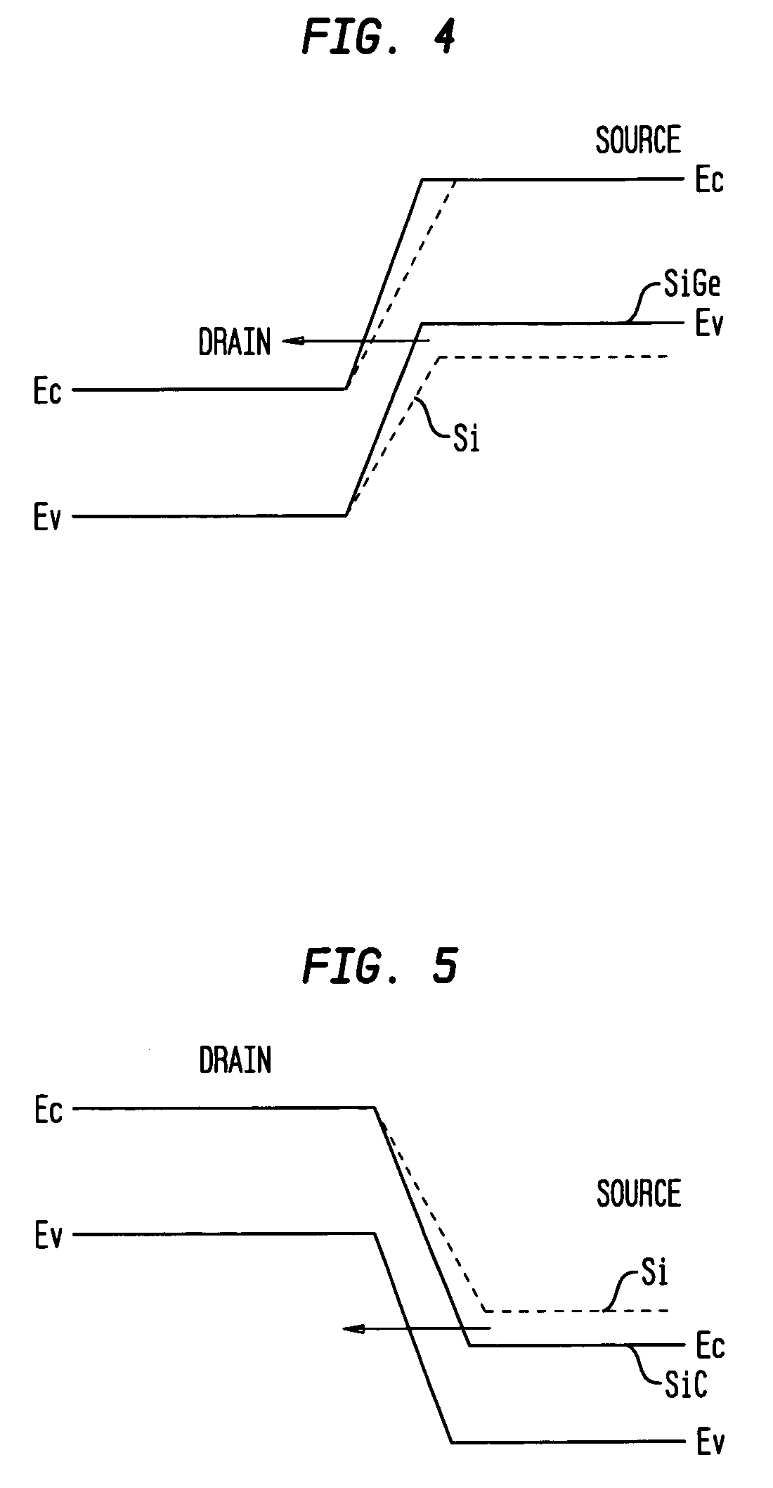
[0008] It has been discovered that the tunneling current of a TFET device depends not only on the abruptness of the source doping gradient, but also on the band gap of the material used for forming the TFET device. Therefore, a heterojunction formed by a suitable semiconductor material of a different band gap can be constructed and arranged to further enhance the junction current in the TFET device. For example, silicon germanium has a smaller band gap than silicon, and it can therefore be used to form the source region of an n-channel TFET device, thereby providing an abrupt junction between the source and channel regions for further enhancing the tunneling current in the n-channel TFET device. On the other hand, silicon carbide can be used to form the source region of a p-channel TFET device for further enhancing the tunneling current in the p-channel TFET device.

Problems solved by technology

As conventional complementary metal-oxide-semiconductor (CMOS) devices are scaling down, the leakage current is increased, and the device performance is degraded, due to increased short channel effects.

Method used


Image

  • Heterojunction tunneling field effect transistors, and methods for fabricating the same
  • Heterojunction tunneling field effect transistors, and methods for fabricating the same
  • Heterojunction tunneling field effect transistors, and methods for fabricating the same

Examples


Embodiment Construction

[0032] In the following description, numerous specific details are set forth, such as particular structures, components, materials, dimensions, processing steps and techniques, in order to provide a thorough understanding of the present invention. However, it will be appreciated by one of ordinary skill in the art that the invention may be practiced without these specific details. In other instances, well-known structures or processing steps have not been described in detail in order to avoid obscuring the invention.

[0033] It will be understood that when an element as a layer, region or substrate is referred to as being “on” or “over” another element, it can be directly on the other element or intervening elements may also be present. In contrast, when an element is referred to as being “directly on” or “directly over” another element, there are no intervening elements present. It will also be understood that when an element is referred to as being “beneath” or “under” another elem...


PUM


Abstract

The present invention relates to a heterojunction tunneling effect transistor (TFET), which comprises spaced apart source and drain regions with a channel region located therebetween and a gate stack located over the channel region. The drain region comprises a first semiconductor material and is doped with a first dopant species of a first conductivity type. The source region comprises a second, different semiconductor material and is doped with a second dopant species of a second, different conductivity type. The gate stack comprises at least a gate dielectric and a gate conductor. When the heterojunction TFET is an n-channel TFET, the drain region comprises n-doped silicon, while the source region comprises p-doped silicon germanium. When the heterojunction TFET is a p-channel TFET, the drain region comprises p-doped silicon, while the source region comprises n-doped silicon carbide.

Description

FIELD OF THE INVENTION [0001] The present invention relates to tunneling field effect transistors, and methods for forming the same. More specifically, the present invention relates to heterojunction field effect transistors that comprise source and drain regions of different semiconductor materials for improved tunneling current. BACKGROUND OF THE INVENTION [0002] As conventional complementary metal-oxide-semiconductor (CMOS) devices are scaling down, the leakage current is increased, and the device performance is degraded, due to increased short channel effects. New devices are needed to overcome these problems without requiring new materials and process steps. [0003] The tunneling field effect transistor (TFET) is a quantum mechanical device that shows reduced short channel effects and smaller leakage currents compared to standard complementary metal-oxide-semiconductor (CMOS) devices. FIG. 1 shows an exemplary n-channel TFET 10 that is located in a p-well formed in a semiconduct...

Claims


Application Information

Patent Timeline
Patent Type & Authority Applications(United States)
IPC IPC(8): H01L21/336
CPCH01L29/165H01L29/78H01L29/7391H01L29/66356
Inventor CHEN, XIANGDONGYANG, HAINING S.
Owner IBM CORP
Learn More