
Lock and key bonding system

a key and lock technology, applied in the field of lock and key bonding system, can solve the problems of reducing the sales of legitimate products, weak compact bonding, and stealing, and achieve the effect of avoiding warranty fraud and reducing the temptation of thieves

Inactive Publication Date: 2007-08-02
SIERRA MADRE MARKETING GROUP
View PDF13 Cites 0 Cited by
  • Summary
  • Abstract
  • Description
  • Claims
  • Application Information

AI Technical Summary

Benefits of technology

[0034]In addition, certain aftermarket parts such as specialty wheels attract thieves. Modifications to a vehicle and custom fit of specialty components that will only fit on that individual vehicle may significantly reduce the temptation of thieves.
[0035]The assembly of vehicles having parts that will only fit back on the original would significantly deter theft and may provide a way for vehicle manufacturing companies to avoid warranty fraud.

Problems solved by technology

It should be noted that some parts will only fit one way with each other anyway and in these instances modification of part design for one way assembly provides little if any benefit.
This may result in a strong compact bond having a one way fit.
These counterfeit products may be labeled as originals and sold to unsuspecting consumers.
This may result in reduced sales of legitimate products and may even add to product liability from the use of the inferior counterfeit product.
Unfortunately, holograms are plentiful and there are so many different credit cards out there, placing any hologram on a counterfeit credit card would fool many individuals.
The process involves expensive metallization equipment and therefore would be expensive to reproduce.
A significant portion of vehicle theft occurs because the thieves want the parts of the vehicles themselves.
Often when a car is stolen it is taken to a “chop shop” (an illegal operation of dismantling stolen cars for their parts).
1. The value of the parts often exceeds the value of the car.
2. Individual parts are smaller and therefore easier to conceal.
3. Registration and vehicle identification numbers make stolen cars difficult to sell.
In addition, certain aftermarket parts such as specialty wheels attract thieves.
Furthermore, is such parts are stolen, their unique geometry may be used as a sort of fingerprint for positive identification by investigating authorities.

Method used


Image

  • Lock and key bonding system
  • Lock and key bonding system
  • Lock and key bonding system

Examples


Embodiment Construction

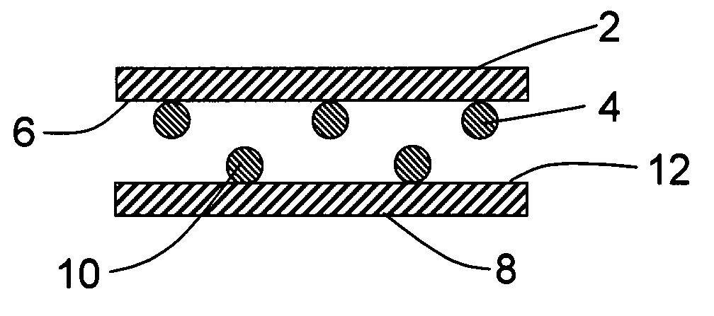
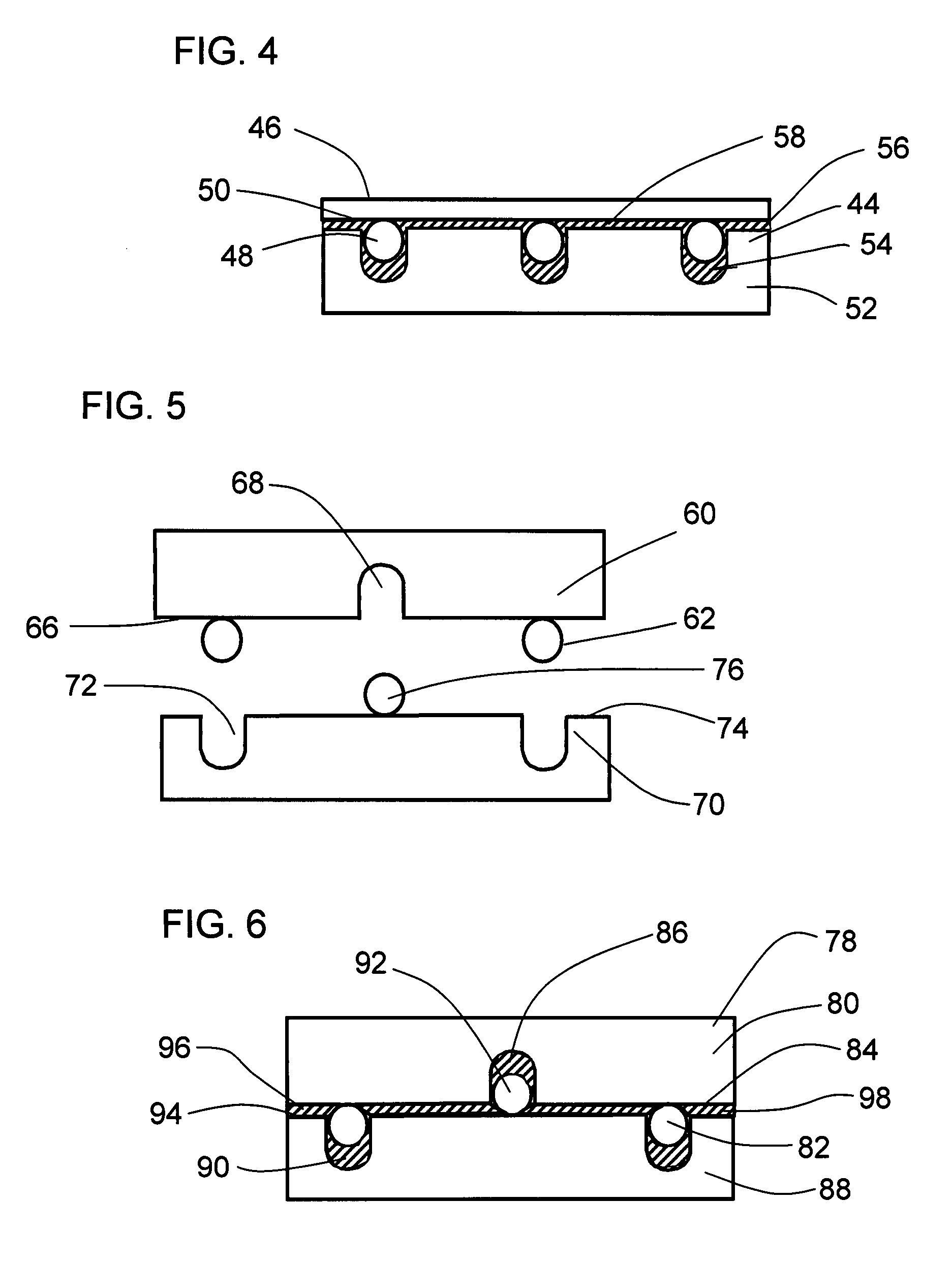
[0062]FIG. 1 shows two surfaces having protrusions facing each other with interposing surface bonding geometry. This particular geometry is suitable for numerous bonding applications. Top laminate portion 2 is shown having protrusions 4 extending in an outward direction from bottom surface portion 6 of top laminate portion 2. Also shown is bottom laminate portion 8. Bottom laminate 8 is shown having protrusions 10 extending in an outward direction from top portion 12 of bottom laminate 8.

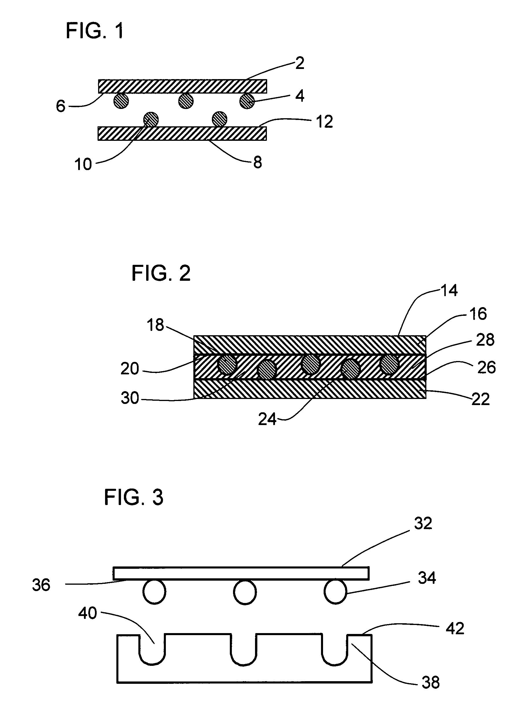
[0063]FIG. 2 shows a sectional view of two surfaces having protrusions interposed with a bonding agent. Such bonding agents include polymers such as epoxy and polyester as well as other materials including closed cell foam. Bonded construction 14 is shown having top laminate portion 16 having protrusions 18 extending in an outward direction from bottom surface 20 of top beaded laminate portion 16. Also shown is bottom laminate portion 22 having protrusions 24 extending in an outward direction from t...


PUM

PropertyMeasurementUnit
thicknessaaaaaaaaaa
basicaaaaaaaaaa
surface adhesionaaaaaaaaaa

Abstract

Interlocking bonding surfaces for use with bonding agents are disclosed having unique lock and key geometries that may be matched to each other in one or more ways. One part may have holes in a specific configuration while the matched part has protrusions or alternatively, one part may have both protrusions and holes that interlock with those of the other matching part. Such configurations provide a one way fit between parts in addition to providing authentication and control of specific components.

Description

CROSS REFERENCE TO RELATED APPLICATIONS[0001]This non-provisional application claims benefit of the provisional application filed on Feb. 1, 2006 having U.S. application number 60 / 764,089.BACKGROUND OF THE INVENTION[0002]1. Field of the Invention[0003]This invention relates to bonding surfaces together with bonding agents. More particularly this invention relates to bonding surfaces having unique geometries providing one way fit characteristics along with numerous possible configurations. The bonding surfaces of this invention provide a large number of combinations based on protrusion and space interlocking geometries. Numerous combinations are provided by the matching location of protrusions and spaces / holes on the individual bonding surfaces themselves. The large number of matched bonding surface combinations of this invention provides the benefit of part verification, authentication of origin, tamper evident constructions, and anti-counterfeit protection.[0004]2. Description of t...

Claims


Application Information

Patent Timeline
Patent Type & Authority Applications(United States)
IPC IPC(8): B31B1/60
CPCB32B7/04B32B7/08F16B11/006Y10T156/10B32B27/38B32B3/30B32B5/18
Inventor MIEKKA, FRED N.
Owner SIERRA MADRE MARKETING GROUP
Learn More