Containment structures and methods

Inactive Publication Date: 2007-07-26
EHSANI MOHAMMAD R +2
View PDF10 Cites 18 Cited by
  • Summary
  • Abstract
  • Description
  • Claims
  • Application Information

AI Technical Summary

Benefits of technology

[0014] The invention also relates to structures and methods to minimize future, or to abate existing, corrosion by forming a substantially air-tight seal that prevents oxidation. Furthermore, the invention relates to a method for applying or retrofitting FRP systems to containers, including electrolytic cells, so as to better electrically insulate the same. Reduction in corrosion and leaks also reduces damage and maintenance to the floor, as well as concerns over safety and environmental issues relating to solutions being present outside of the containment structure (e.g., slipping, solution leaking to soil, etc.)
[0016] Preferably, the composition of the top-coat is selected be resistant to the chemical(s) contained with in the cell. In addition, the FRP fabric may include one or more layers of chopped fiber, commonly referred to as mat. The mat serves several functions, including providing a protective layer to prevent damage to the fibers that may occur from the falling of electrodes and providing a smooth finished surface that will prevent formation of pin holes. Other options include using materials with separate layers of mat to provide leak proofing to the system. Preferably, the fabric layer includes fibers oriented at both zero and 90 degrees, thereby reproducing the structure of the horizontal and vertical rebar in reinforcing a concrete cell wall or floor. Single or multiple layers of fabric may be utilized.
[0018] In another aspect of the invention, the liner serves as an insulator that will prevent flow of stray current from the cells into beams, columns, footings, and other surrounding structures. Hence, the invention provides a measure of added efficiency and safety.

Problems solved by technology

Basic storage tanks for these substances typically are fabricated from steel, reinforced concrete, or glass fiber reinforced plastic, and, depending upon the environment of the installation and the substances being contained, can be subject to corrosion and / or leakage.
Because leakage of hazardous or otherwise detrimental material often is damaging to the environment and costly and time-consuming to remedy, several systems have evolved to better contain such substances.
While certain thermoplastic polyester elastomers can be formulated to be highly impervious to volatile and / or corrosive materials, sheets of such thermoplastics typically do not exhibit sufficient strength and resistance to puncture as is desirable for use as primary or secondary containments.
While most new plants make use of the polymer concrete cells, older plants have delayed discarding the concrete-and-liner cells as long as they continue to operate profitably, albeit with larger maintenance costs.
As one might expect, these older cell structures are particularly prone to problems when liner damage occurs.
Damage to the liner and underlying structure can occur in a variety of ways.
During operations, the cells are subjected to falling electrodes, misaligned cranes that gauge or cut the sides of the liner when the electrodes are removed, and breakdown over time as the liner ages and becomes cracked and brittle.
Once a liner is damaged, electrolyte will leak onto the concrete cell walls and begin to erode the concrete and rebar (the horizontal and vertical steel rods that provide strength to the cement of the cell), eventually compromising the cell's structural integrity.
The wood floors of older cells also see damage as a result of being saturated with solution, which can cause the wood to warp and sag.
Since a liner covers the cell structure, leaks can easily go undetected for long periods of time.
This costs the operation in lost production and in labor and materials used for repair or replacement.

Method used


Image

  • Containment structures and methods
  • Containment structures and methods
  • Containment structures and methods

Examples


Embodiment Construction

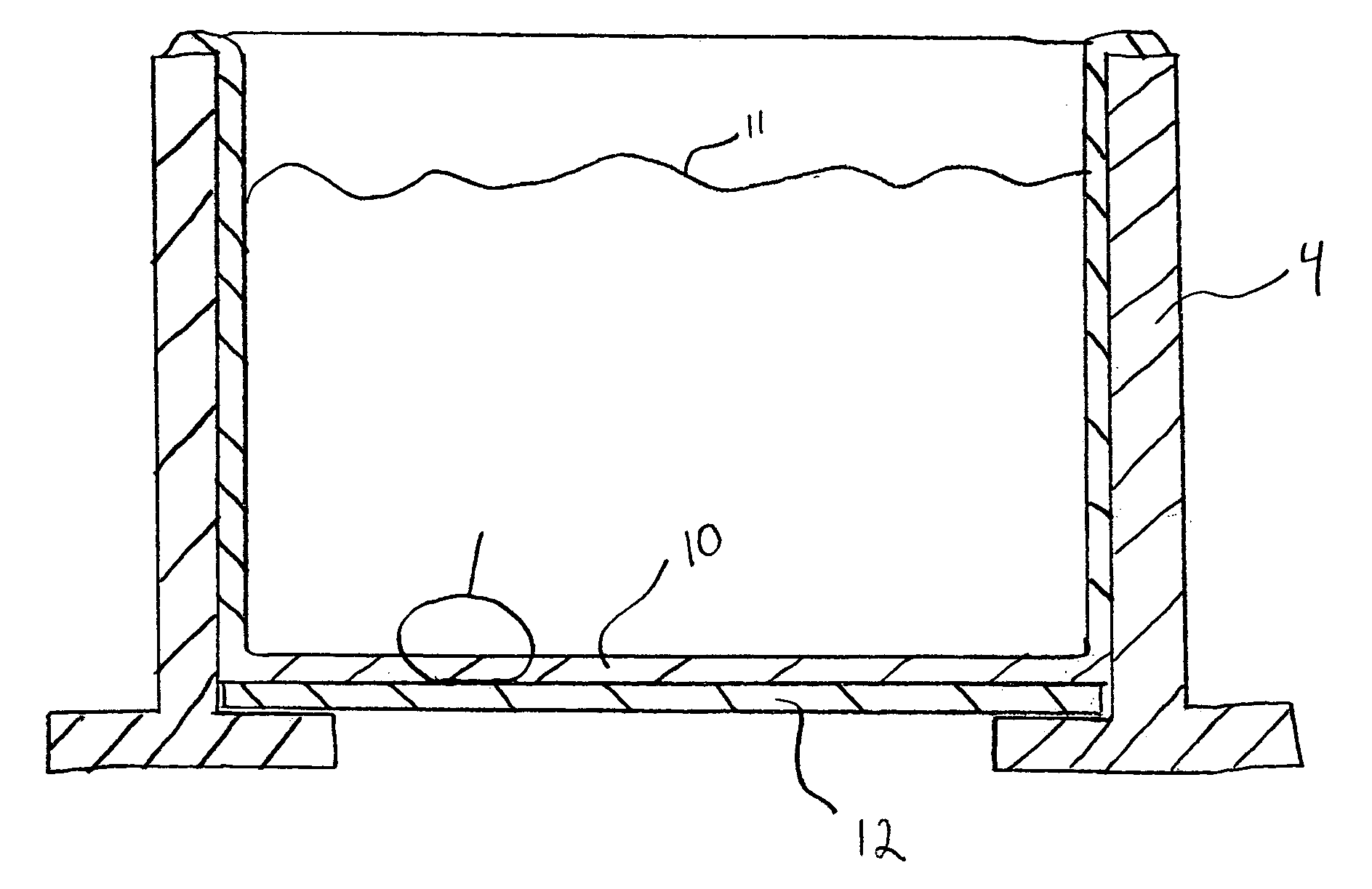
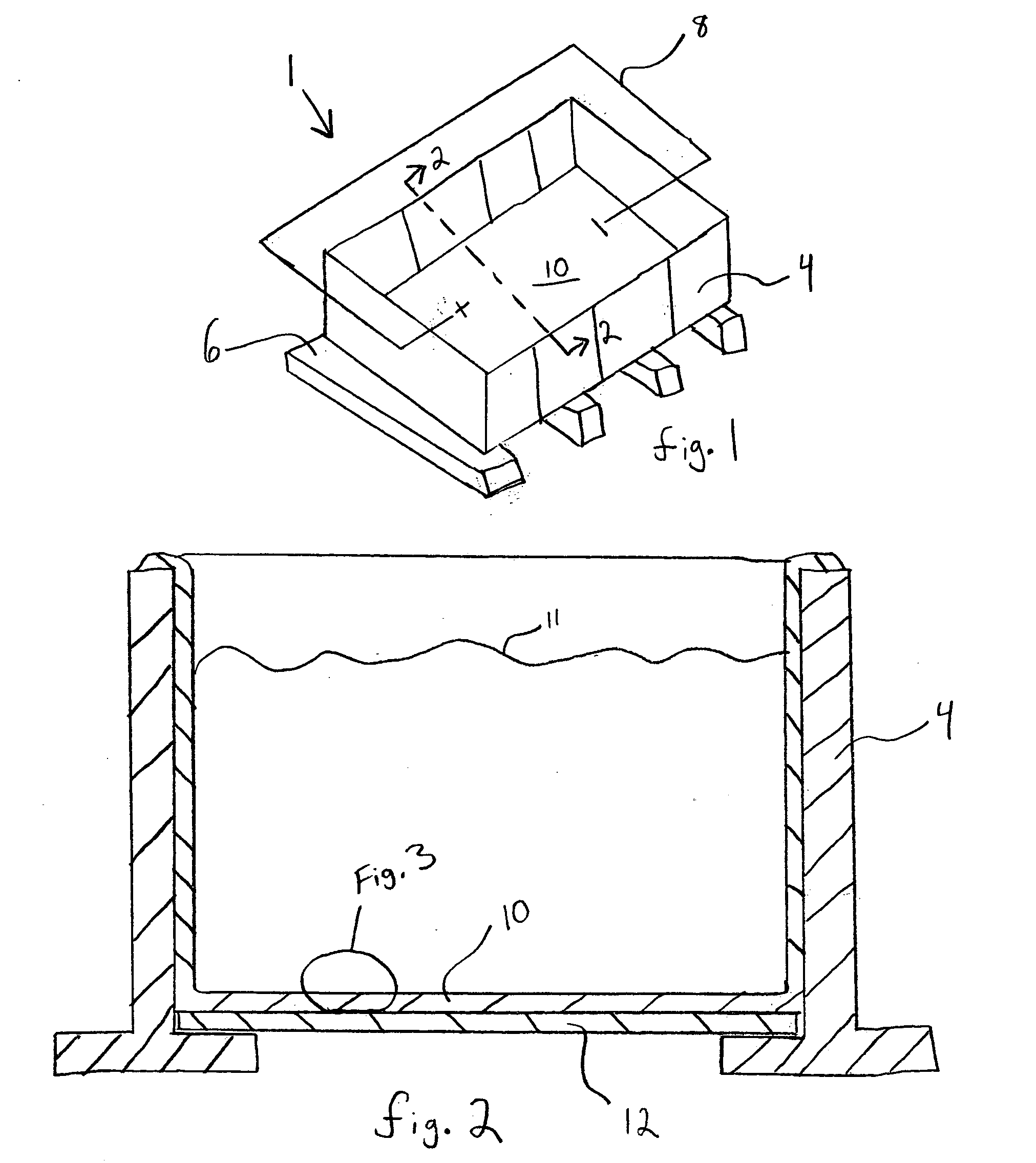
[0025] As shown in FIGS. 1-3, the invention generally relates to a container having a permanently and substantially continuously affixed liner. For example, the container may be an electrolytic cell 1. The cell 1 includes a containment structure 4 including a base 6. Preferably, the containment structure and base are composed of concrete or polymer concrete. A means for providing electrical current such that a circuit 8 is formed preferably takes the form of a metal cathode and anode connected to a source of electricity. Permanently bonded upon the interior of the structure 4 is a resin and Fiber Reinforced Polymer (FRP) liner 10 that is at least partially contacted by liquid 11.

[0026] As seen in the cross-sectional view of FIG. 2, the liner 10 is bonded at every point in a substantially continuous manner so that any breach is completely localized to the damaged site. Such localized containment of any breach of the liner is extremely important in the electrolytic cell industry beca...


PUM


Abstract

An electrolytic cell or other containment structure having a permanent resin and Fiber Reinforced Polymer liner. The liner is permanently adhered to a cleaned and primed surface and contains one or both of woven fabric and chopped fibers.

Description

BACKGROUND OF THE INVENTION [0001] 1. Field of the Invention [0002] This invention relates generally to containment structures, and, more particularly, to containment structures and methods featuring a liner for reinforcing a container, tank, or cell and for protecting against its corrosion and the leakage of its contents. [0003] 2. Description of the Related Art [0004] Underground and aboveground storage containers or tanks are widely used for containment of fuels and chemicals. Basic storage tanks for these substances typically are fabricated from steel, reinforced concrete, or glass fiber reinforced plastic, and, depending upon the environment of the installation and the substances being contained, can be subject to corrosion and / or leakage. [0005] In the mining industry, large tanks or containers of acidic solution (so-called “electrolytic cells”) are used in the electrowinning and electrorefining of metals, such as copper, zinc, nickel, cobalt, and manganese. In these processes...

Claims


Application Information

Patent Timeline
IPC IPC(8): B60R21/16
CPCB65D90/022Y10T428/1362B65D90/044
Inventor EHSANI, MOHAMMAD R.MACDONALD, STACEYPAUZE, DENNIS A.
Owner EHSANI MOHAMMAD R
Why Eureka
Try Eureka