Battery pack protection circuit and battery pack

Active Publication Date: 2007-07-19
MURATA MFG CO LTD
View PDF0 Cites 25 Cited by
  • Summary
  • Abstract
  • Description
  • Claims
  • Application Information

AI Technical Summary

Benefits of technology

[0017] The present invention improves upon the prior art by providing, for example, a battery pack protection circuit in which two means of protection against overcurrent and overheating are provided without requiring a protective element, such as a polymer PTC element, in series in the charge / discharge path of a battery cell and further without requiring a third switching element that is controlled by a positive temperature coefficient or negative temperature coefficient thermistor, and by providing a battery pack including such a battery pack protection circuit.
[0018] The present invention further provides a protection circuit which overcomes the shortcomings associated with the known techniques described above and in which a resistance component is not required in series with the current path, thus not resulting in an increase in loss, and which can protect a battery pack reliably even if local overheating occurs.

Problems solved by technology

If the switching elements 134a and 134b are abnormally overheated, resulting in thermal runaway or failure, even if the protective control circuit 133 detects the abnormality, since the switching elements 134a and 134b cannot be shut off, the protection function may not work.
Thus, when the polymer PTC element is incorporated into a battery pack, it is necessary to perform manual soldering and welding, resulting in an increase in manufacturing cost.
Furthermore, even if a temperature fuse is used as the protective element 2, because of its heavy overall weight and large volume and because it again is of a lead type, the manufacturing cost is increased, as in the case of the polymer PTC element.
Moreover, when the temperature fuse is disconnected due to an abnormal temperature, it cannot be reused.
Furthermore, the protection function does not work against overcharge until the battery cell overheats and the protective element is activated.
Consequently, there is a possibility that the outer resin case of the battery pack may be deformed or melted due to abnormal overheating.
However, since the third switching element is inserted in series into the charge / discharge current path of the battery cell, an expensive power FET is required, and the cost is increased.
Furthermore, use of the third switching element increases the possibility of thermal runaway or failure due to abnormal overheating.
Consequently, it is not possible to detect a local increase in temperature in the battery pack.
Consequently, if only the switching element is in a high-temperature state, the entire battery pack may not yet reach a high-temperature state that allows the protection function to work.
In such a case, the switching element is subjected to thermal runaway.
Therefore, in some cases, the temperature of the entire battery pack is increased after the thermal runaway of the switching element, and even if it is attempted to control the switching element by the protective control circuit, the control may not be possible.
That is, in the protection circuit described in Patent Document 3, since it is not possible to detect local overheating to protect the circuit, the protection function is not sufficient.

Method used


Image

  • Battery pack protection circuit and battery pack
  • Battery pack protection circuit and battery pack
  • Battery pack protection circuit and battery pack

Examples


first embodiment

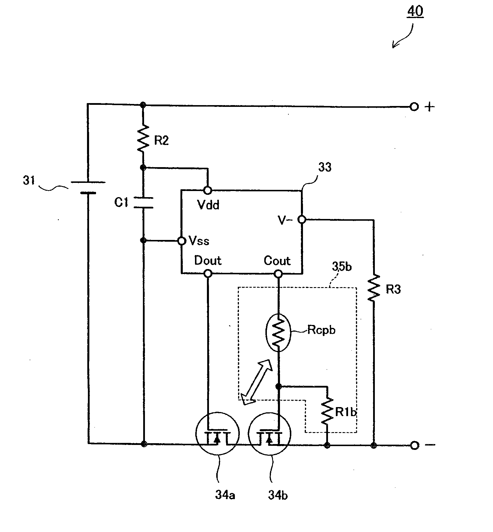
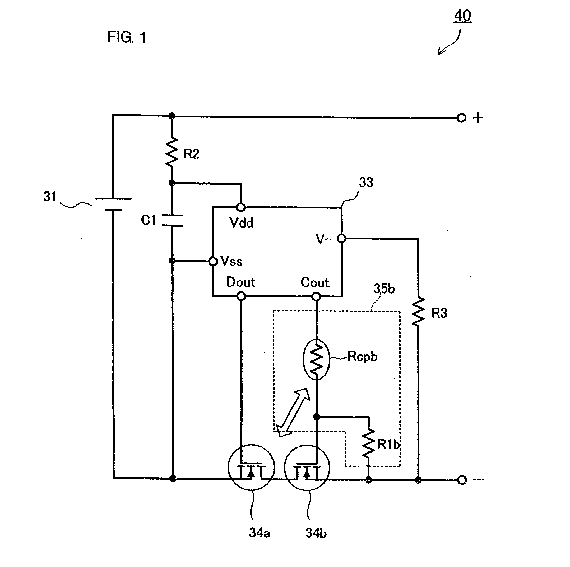
[0064] A structure of a battery pack protection circuit and a battery pack will be described below with reference to FIG. 1.

[0065]FIG. 1 is a circuit diagram of a battery pack 40 provided with a battery pack protection circuit. A first switching element 34a and a second switching element 34b are disposed in series in a charge / discharge path of a battery cell 31. In a protective control circuit 33, a grounding terminal Vss thereof is connected to a negative pole of the battery cell 31, and a terminal Vdd is connected via a resistor R2 to a positive pole of the battery cell 31. A capacitor C1 for eliminating a noise signal is connected between the terminals Vdd and Vss. A resistor R3 is connected between a terminal V− of the protective control circuit 33 and a minus (−) terminal of the battery pack 40.

[0066] The first and second switching elements 34a and 34b each comprise an FET. The protective control circuit 33 is composed of a semiconductor integrated circuit and is provided wit...

second embodiment

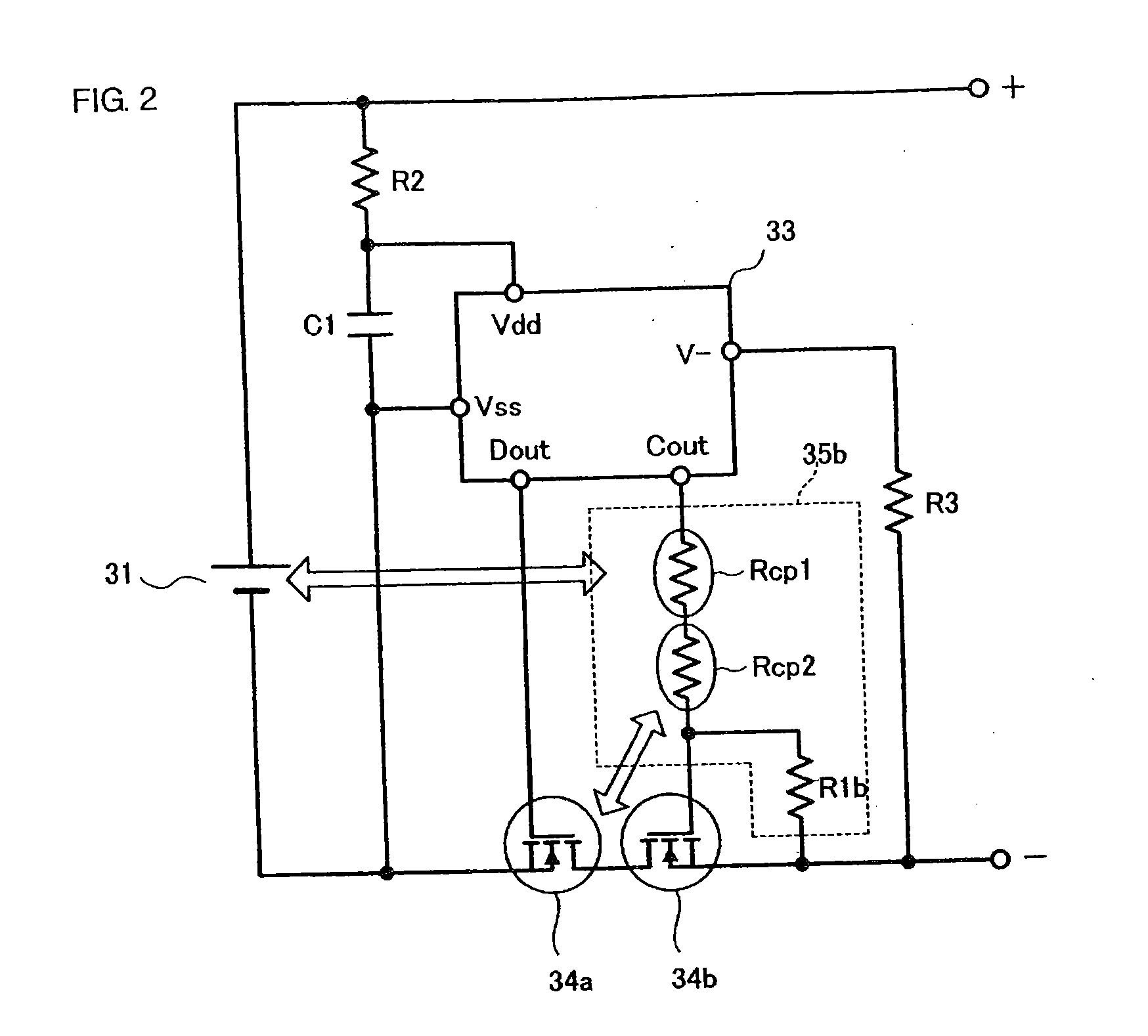
[0077] A structure of a battery pack protection circuit and a battery pack will be described below with reference to FIG. 2.

[0078] In the example shown in FIG. 1, a single ceramic positive temperature coefficient thermistor is used. In the second embodiment, a plurality of ceramic positive temperature coefficient thermistors which are respectively thermally connected to different parts are used. That is, a series circuit including a positive temperature coefficient thermistor Rcp1 for battery cell use and a positive temperature coefficient thermistor Rcp2 for switching element use is inserted between a gate control terminal Cout of a protective control circuit 33 and a gate of a second switching element 34b. A resistor R1b is connected between a source and the gate of the second switching element 34b. The resistor R1b and the two ceramic positive temperature coefficient thermistors Rcp1 and Rcp2 constitute a switching element control circuit 35b. The remainder of the structure is t...

third embodiment

[0081] A structure of a battery pack protection circuit and a battery pack 40 will be described below with reference to FIG. 3.

[0082] In the examples shown in FIGS. 1 and 2, the switching element control circuit 35b is provided in the control signal path of the second switching element 34b. In the third embodiment, a switching element control circuit 35a is also provided in the control signal path of the first switching element 34a. That is, a ceramic positive temperature coefficient thermistor Rcpa which is thermally connected to the first switching element 34a is inserted between the gate of the first switching element 34a and the gate control terminal Dout of the protective control circuit 33, and a resistor R1a is connected between the gate and source of the switching element 34a. The resistor R1a and the ceramic positive temperature coefficient thermistor Rcpa constitute the switching element control circuit 35a. The remainder of the structure is the same as that shown in FIG....


PUM


Abstract

A battery pack includes a first switching element which shuts off a discharging current flowing to a battery cell and a second switching element which shuts off a charging current. A positive temperature coefficient thermistor is inserted between a gate control terminal of a protective control circuit and a gate of at least one of the switching elements, and a resistor is connected between the gate and a source of the switching element. The positive temperature coefficient thermistor is thermally connected to one or more of the first and second switching elements and / or to the battery cell. Thus, an abnormally overheated state of one or more of the switching elements or the battery cell leads to an increase in the resistance of the positive temperature coefficient thermistor causing shut-off of the switching elementthereby protecting the battery pack.

Description

CROSS-REFERENCE TO RELATED APPLICATIONS [0001] This is a continuation of PCT / JP2005 / 009326 filed May 23, 2005, which claims priority of JP2004-178440 filed Jun. 16, 2004 and JP2004-206244 filed Jul. 13, 2004, incorporated by reference.BACKGROUND OF THE INVENTION [0002] 1. Technical Field [0003] The present invention relates to protection circuits which protect battery packs including secondary batteries from overcurrent and abnormal overheating. More particularly, the invention relates to battery pack protection circuits including positive temperature coefficient thermistors and switching elements, and battery packs related thereto. [0004] 2. Background Art [0005] Patent Document 1: Japanese Unexamined Patent Application Publication No. 2000-152516, incorporated by reference. [0006] Patent Document 2: Japanese Unexamined Patent Application Publication No. 2002-8608, incorporated by reference. [0007] Patent Document 3: Japanese Unexamined Patent Application Publication No. 2004-12084...

Claims


Application Information

Patent Timeline
IPC IPC(8): H02J7/00H02H5/04H02H7/18
CPCH02J7/0031H02H5/042H02H3/085H02H7/18H02J7/00309H02J7/00304H01M50/581H01M50/583H01M2200/106
Inventor TSUBAKI, SHUJIMIYAGAWA, KAZUTOIKEDA, YUTAKA
Owner MURATA MFG CO LTD
Why Eureka
Try Eureka