
Method and apparatus for connecting small diameter tubing

a technology of small diameter tubing and connecting apparatus, which is applied in the direction of hose connection, laboratory glassware, instruments, etc., can solve the problems of difficult to verify the integrity of the coupling, difficult use of high-pressure fittings, and strong friction, so as to avoid the undesirable condition of excess mechanical constraints and high tolerance

Active Publication Date: 2007-07-19
NEW OBJECTIVE INC
View PDF23 Cites 24 Cited by
  • Summary
  • Abstract
  • Description
  • Claims
  • Application Information

AI Technical Summary

Benefits of technology

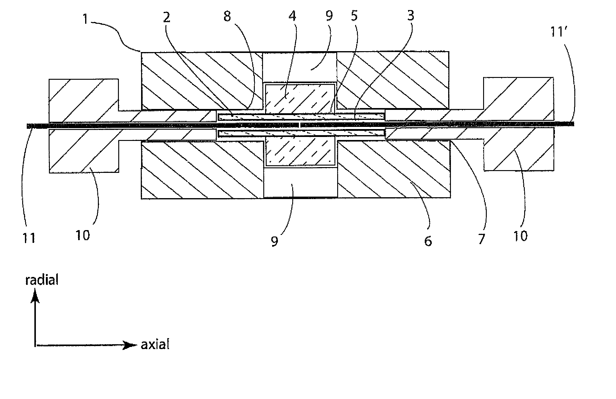
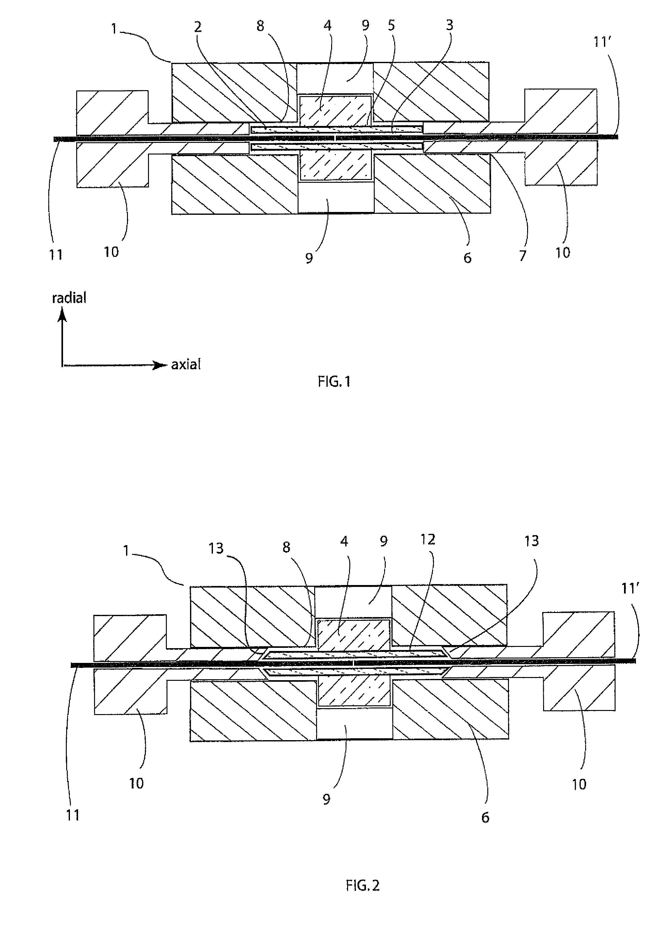
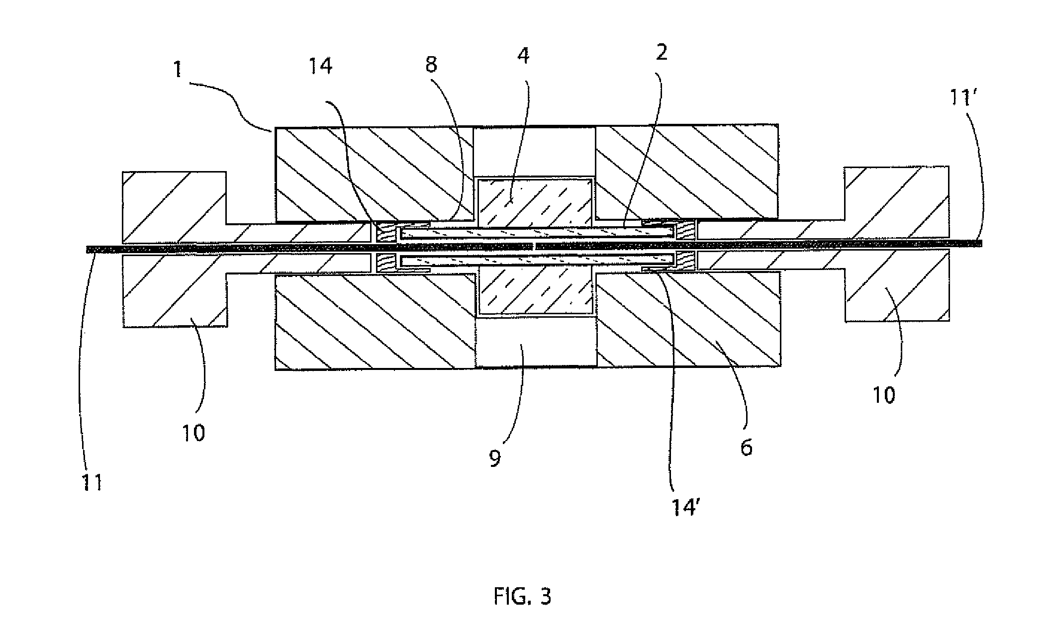
[0011] The union body in this case has a geometry and dimensions which enable it to fit within the slot or recess of the union housing, and does not require threaded ends, as the threaded ends of the union housing can be used to engage the compression elements. Most preferably the union body has both a cross-sectional geometry and outer dimensions which allow it to float freely within the union housing. The amount of float is, at a minimum, equal to one half the outer diameter of the tubes being joined. When the elastomer core is compressed and the inner diameter is reduced the union body will than come into alignment with the outer surface of the tubes being joined. This creates a connection in which the elastomer is self-aligning to the outer surfaces of the tubing being joined. The floating insert avoids the undesirable condition of excess mechanical constraint, ensuring co-axial alignment of the tubes and eliminates the need for parts manufactured to extremely high tolerance.

Problems solved by technology

The interference fit between the ID of the sleeve and OD of the tubing results in strong friction between the coupling sleeve and the capillary tubing; holding the tubing in place.
The high-pressure fittings can be difficult to use and often have many parts to assemble.
It is typically difficult to verify the integrity of the coupling, which often requires partial disassembly.
This design overcomes the assembly problem of a conventional frusto-conical union, however, a significant amount of swept volume is added to the connection.
A significant limitation of the apparatus disclosed by Lowe (U.S. Pat. No. 822,530) is a mechanical design that is overly constrained in the axis of the connected tubes.
Use at high pressures (e.g. greater than 100 to 150 psi) is not routinely possible since the sleeve expands and distorts under pressure and the assembly does not hold together.

Method used


Image

  • Method and apparatus for connecting small diameter tubing
  • Method and apparatus for connecting small diameter tubing
  • Method and apparatus for connecting small diameter tubing

Examples


example 1

Union Body with Housing

[0103] A union body was fabricated from cut lengths of material. The body was fabricated from cylindrical glass tubing, having an OD of 0.290″ and an ID of 0.063″ which was cut and polished to a length of 0.20″. The core was fabricated from cylindrical FEP tubing, having an OD of 0.062″ and an ID of 0.016″, cut to a length of 0.40″. The core was etched in FluoroEtch solution (sodium in naphthalene) for a period of 1 minute, and then rinsed with distilled water. The core was placed inside the union body and the two were bonded together using Norland Optical Adhesive 83H (a methacrylate based UV curable photopolymer adhesive), following standard manufacturer protocols for UV exposure and polymer curing. Typically the assembly was exposed to UV light from a low wattage UV lamp for 30-60 minutes, and allowed to cure overnight in an oven at approx. 100° C. The union body had the geometry shown in FIG. 5a.

[0104] After curing, the union body was placed inside a sta...

example 2

Opto-Electronic Detection of Union

[0106] As shown in FIG. 14, light from a laser diode 27 (670 nm, 4 mW) was passed though a focusing lens 28 and an optical density filter 29 (OD 3) yielding an elliptically focused beam having the approximate dimensions of 1.0×0.4 mm at the focal plane of the lens. A union housing body 53 (without the housing as in FIG. 22), having a core fabricated from 0.016″ I.D.×0.062″ O.D. FEP tubing, and a union housing body made from clear, square polymethylmethacrylate (PMMA) polymer having a cylindrical bore 0.063″ I.D.×0.150″ long at its center. Since this was a non-housing embodiment, the flat ended compression nuts 10 threaded directly into the clear union housing-body. These fittings had a terminal OD of 0.062″ and could directly compress the core material by extending into the 0.063″ bore of the union body. The union body was placed in this focal plane of the lens, with the long axis of the union parallel and coincident to the 1 mm axis of the beam. A...

example 3

Coupling of Optical Fibers

[0113] The unique properties of the invention permit high efficiency coupling of light from one optical fiber to another. When the elastomer core is compressed, its I.D. reduces to the O.D. of the fibers being connected. Furthermore, since the core is one continuous ID, the coaxial alignment of the two fibers will be excellent, and essentially self-aligning.

[0114] In this example a union of the cartridge design (as in FIGS. 4a-c) was used to connect two pieces of small core diameter single mode optical fiber. The apparatus is shown in FIG. 16.

[0115] Light from a laser diode 26 (670 nm, 4 mW) was launched into a first single mode optical fiber 36 (3.2 μm O.D. core, 125 μm O.D. cladding, 250 μm O.D. polymer jacket, 488 nm design wavelength, cleaved at both ends to 20 cm length) using a fiber coupling stage with a ball lens (Newport Corporation). The free end of fiber 36 was inserted into the union assembly 1, having a 0.010″ I.D.×0.062″ O.D.×0.280″ long FE...


PUM

PropertyMeasurementUnit
pressureaaaaaaaaaa
pressureaaaaaaaaaa
pressureaaaaaaaaaa

Abstract

A union for coupling two or more segments of tubing or optical fiber, having an elastomeric core with two or more tubular sections encased in a through bore of a union body, the ends of the union body bore having compression nuts having through bores for insertion of segments of tubing or optical fiber to be coupled, which, tubular sections, when compressed by the compression nuts, deform radially inwardly to hold and seal the segments of tubing or optical fiber inserted therein.

Description

[0001] This application is a Continuation-In-Part of International Application Number PCT / EP2005 / 018944, filed on 27 May 2005, which claims the benefit of U.S. Provisional Application Ser. No. 60 / 575,249, filed on 28 May 2004, now pending.[0002] This invention pertains to a method and apparatus, referred to as a union, whereby two or more segments of tubing, preferably small-diameter tubing or optical fiber, having a concentric inner bore or optical core, referred to hereinafter as “capillary tubing”, may be efficiently connected. The connection provides for the coupling of the inside bore or core of each segment in a manner by which all extra-tubing volume within said connection is eliminated, referred to as a “zero dead-volume connection”. Furthermore, a preferred embodiment provides an optically clear view of the connection. Thus, a user can immediately verify that the union and segments are properly assembled. Any significant gap or obstruction between the segments will be visib...

Claims


Application Information

Patent Timeline
Patent Type & Authority Applications(United States)
IPC IPC(8): F16L33/00G01N30/60G02B6/38
CPCG02B6/3809B01L3/565B01L2300/0838G01N30/6039
Inventor VALASKOVIC, GARY A.SAWDEY, LEE R.MURPHY, JAMES P.
Owner NEW OBJECTIVE INC
Learn More