Semi-transparent shielding bag formed by translucent barrier statis shielding film
a shielding film and semi-transparent technology, applied in the field of composite films, can solve the problems of difficult deposition of visible light-transmitting metal oxides or non-metal oxides with suitable barriers on substrates
- Summary
- Abstract
- Description
- Claims
- Application Information
AI Technical Summary
Problems solved by technology
Method used
Image
Examples
example 1
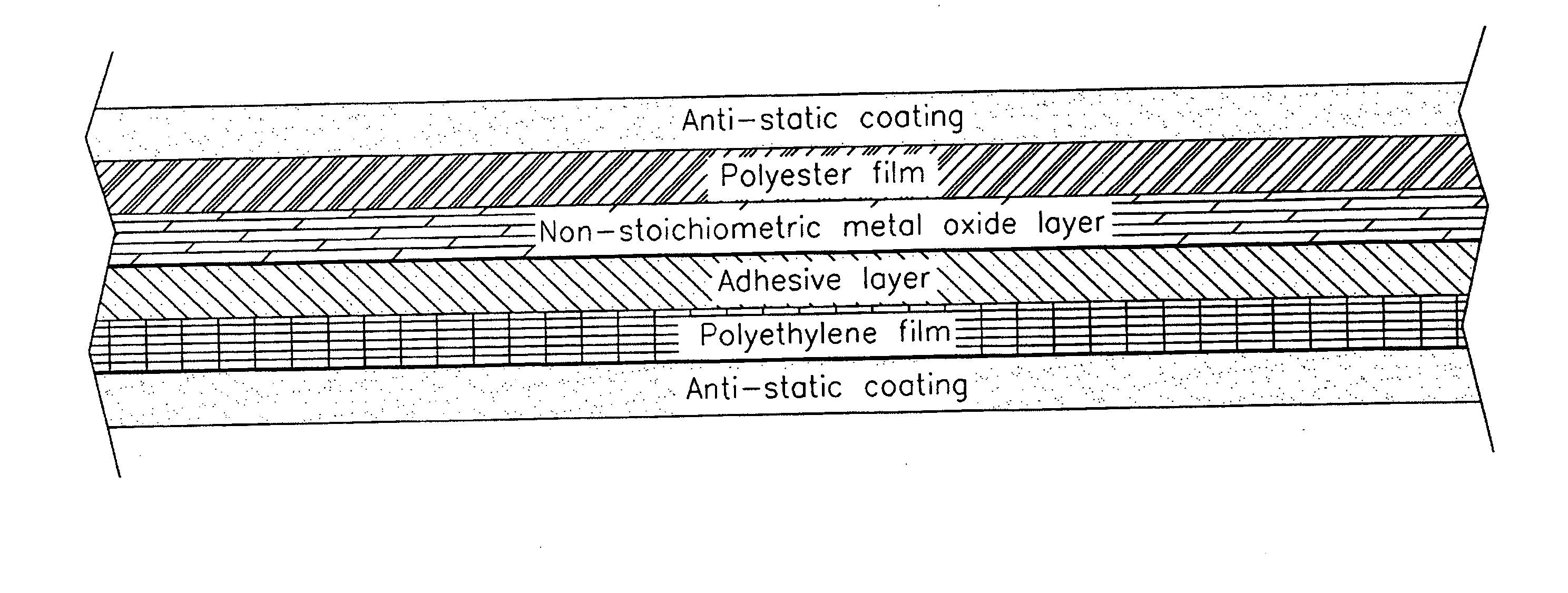
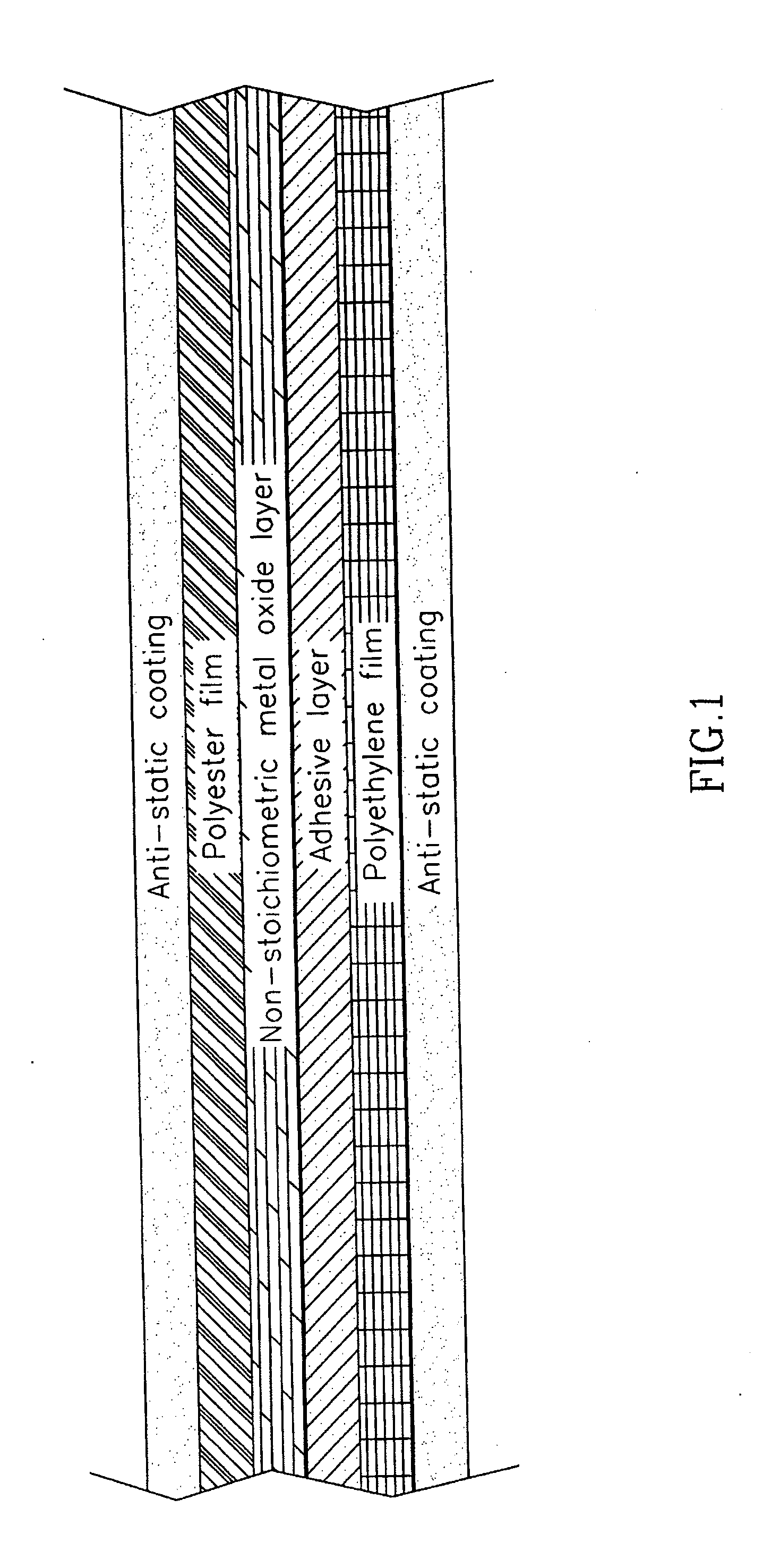
[0043] In one embodiment of the present invention, the composite film comprises the following layers: anti-static wash coat, polyester film, non-stoichiometric aluminum oxide layer, polyurethane adhesive, polyethylene film and anti-static wash coat.
[0044] The composite film may vary in its thickness. Typically, the thickness of each layer ranges as follows:
polyethylene terephthalate substrate10-100micronnon-stoichiometric aluminum oxide layer50-1500Angstrompolyurethane adhesive1.5-10micronpolyethylene film30-200micronanti-static layer0.003-0.01micron
[0045] It will be appreciated that the properties of the composite film may be controlled by varying the thickness of its layers to achieve the desired transmissivity to light, desired strength, desired color etc.
example 2
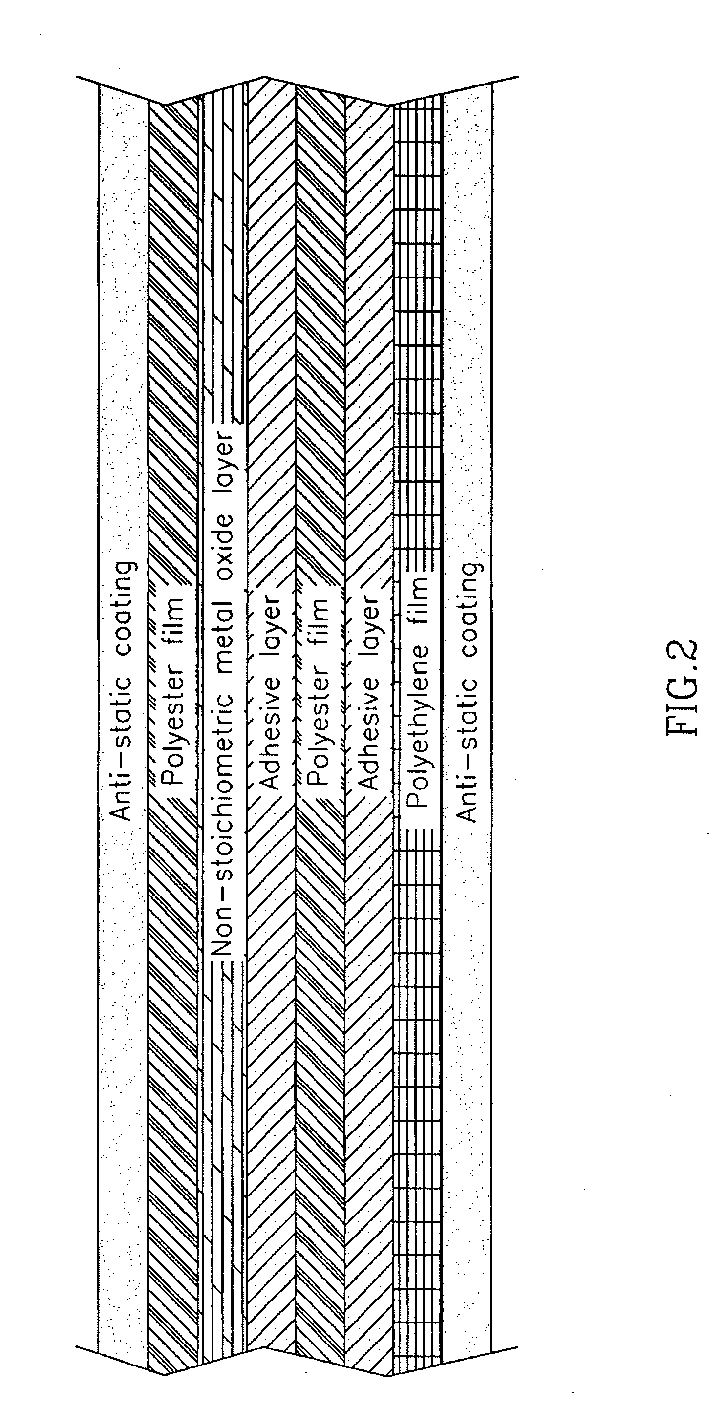
[0046] In one embodiment of the present invention, the composite film comprises the following layers: anti static wash coat, polyethylene terephthalate film, non-stoichiometric aluminum oxide layer, stoichiometric aluminum oxide layer, polyurethane adhesive, polyethylene film and anti static wash coat.
[0047] The composite film may vary in its thickness. Typically, the thickness of each layer ranges as follows:
polyethylene terephthalate substrate10-100micronnon-stoichiometric aluminum oxide layer50-1500Angstromstoichiometric aluminum oxide layer50-3000Angstrompolyurethane adhesive layer1.5-10micronPolyethylene film30-200micronanti static layer0.003-0.01micron
[0048] It will be appreciated that the properties of the composite film can be controlled by varying the thickness of its layers to achieve the desired properties.
[0049] It will be appreciated that the aluminum oxide based layers in composite films having more than one aluminum oxide layer are deposited on their respective su...
example 3
[0050] Samples of the composite film comprising a first layer of polyethylene terephthalate having a thickness of 12 micron, a second layer of non-stoichiometric aluminum oxide having a thickness of 700 Angstrom, a third layer of stoichiometric aluminum protective, a fourth layer of polyurethane adhesive, a fifth layer of polyethylene sealant having a thickness of 60 micron and a sixth layer of ammonium salt anti-static material having a thickness of 0.007 micron were tested for total visible light transmission, electrostatic shielding, surface resistivity and moisture vapor transmission rate. The results are summarized in Table 1:
TABLE 1TestResultUnitsTest ProcedureTotal visible light35-40%ASTM D-1003transmissionElectrostaticVoltsEIA IS 5AshieldingMIL-B-81705CSurface resistivity11Ω / □ASTM D-257 @(checked on PET50% RH (relativelayer)humidity)Moisture Vapor H2O-≦0.015gr / 100ASTM F1249-90Transmission Ratein2 / day(MVTR)100° F.100% RHSurface resistivity11Ω / □ASTM D-257 @(checked on LDPE +...
PUM
| Property | Measurement | Unit |
|---|---|---|
| thickness | aaaaa | aaaaa |
| thickness | aaaaa | aaaaa |
| thickness | aaaaa | aaaaa |
Abstract
Description
Claims
Application Information
 - R&D
- Intellectual Property
- Life Sciences
- Materials
- Tech Scout
- Unparalleled Data Quality
- Higher Quality Content
- 60% Fewer Hallucinations
Browse by: Latest US Patents, China's latest patents, Technical Efficacy Thesaurus, Application Domain, Technology Topic, Popular Technical Reports.
© 2025 PatSnap. All rights reserved.Legal|Privacy policy|Modern Slavery Act Transparency Statement|Sitemap|About US| Contact US: help@patsnap.com


