
Inverter system and detecting device thereof

a technology of inverter system and detecting device, which is applied in the direction of instruments, light sources, electrical devices, etc., can solve the problems of reducing the accuracy of the detecting device, so as to achieve the effect of fewer elements and high precision

Inactive Publication Date: 2007-07-05
DELTA ELECTRONICS INC
View PDF2 Cites 6 Cited by
  • Summary
  • Abstract
  • Description
  • Claims
  • Application Information

AI Technical Summary

Benefits of technology

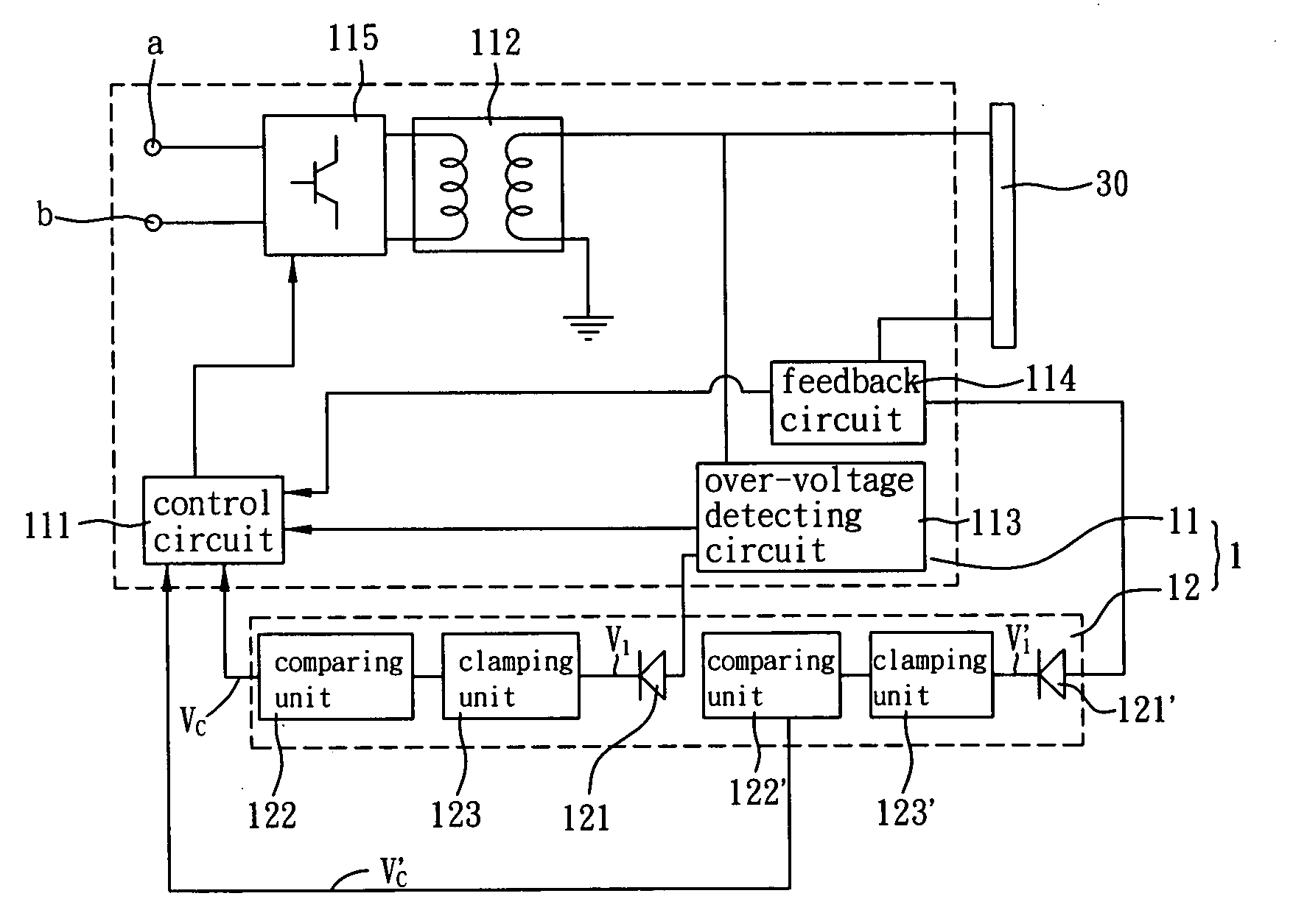
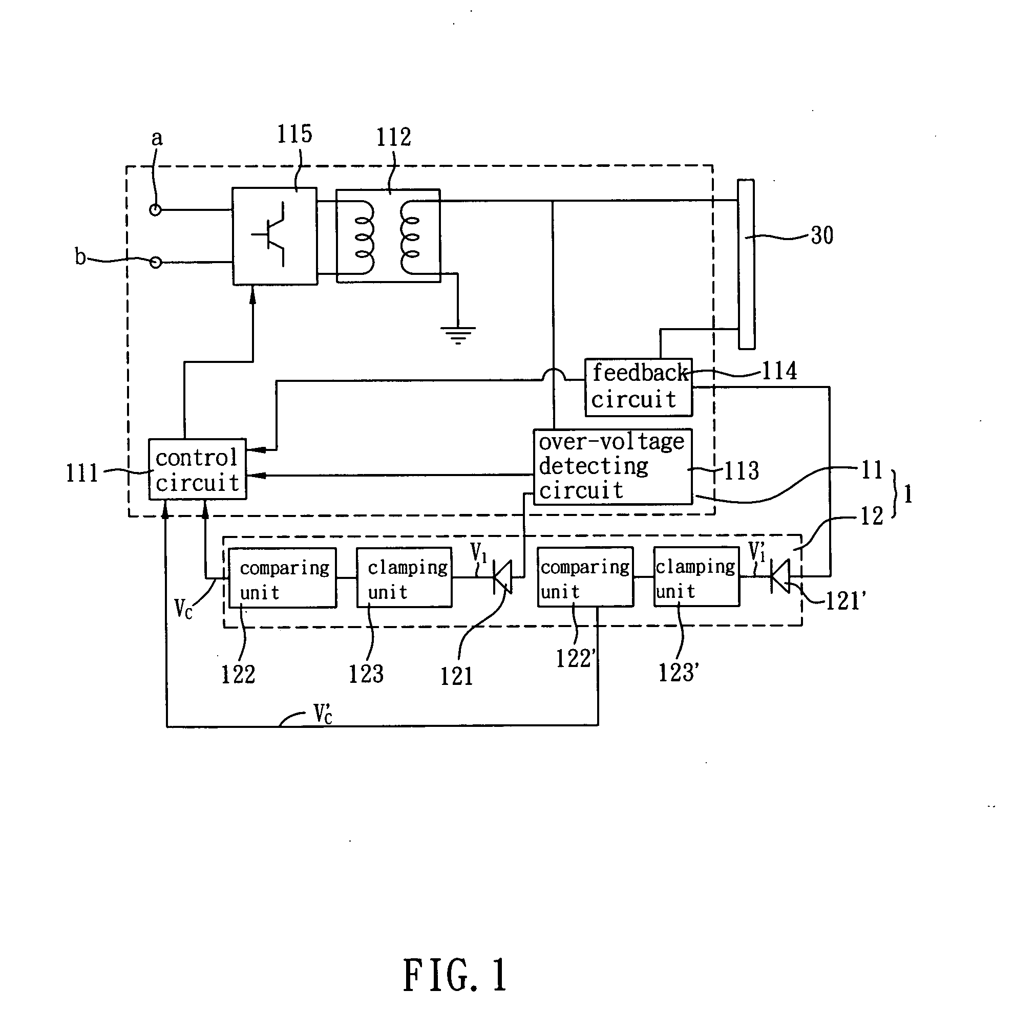
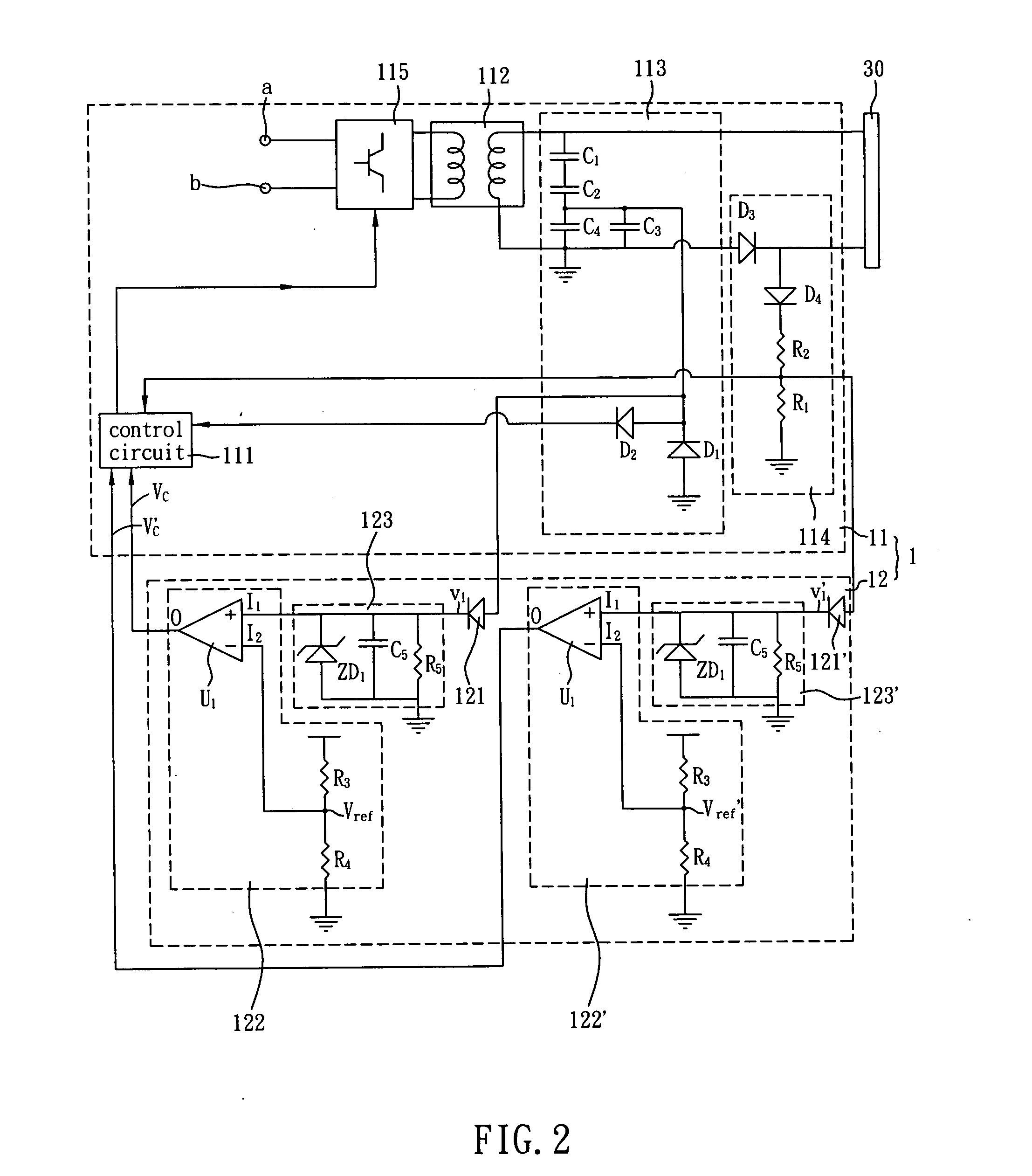
[0012]As mentioned above, the detecting element is used to detect spark phenomena of the inverter system according to the inverter system and the detecting device of the invention, and the inverter system is shut down to protect the inverter system when spark phenomena occur. Compared with the prior art, the invention performs the detection by enabling the detecting element to obtain the voltage signal of the inverter system directly without additional core elements, and thus has the advantages of higher precision and fewer elements.

Problems solved by technology

Because the inverter system is a high voltage circuit, high voltage sparks tend to occur, thereby causing the user to be dangerously shocked or the elements to burn out.
The conventional inverter system only can detect whether the CCFL fails but cannot detect the abnormal condition when the CCFL works normally but the other elements or circuits become abnormal (e.g., when the high-voltage spark occurs) and thus fails to shut the output of the high voltage down in such abnormal conditions.
Thus, the user still may be shocked or the elements may burn out.
However, the above-mentioned method needs to additionally add wires and cores, and the overall interconnection complexity and the number of elements are increased.
In addition, the dimension of the wire and the distance between the wire and the high-voltage loop cannot be easily controlled.
As a result, the magnetic flux change may be not precise enough, thereby influencing the detection result.

Method used


Image

  • Inverter system and detecting device thereof
  • Inverter system and detecting device thereof
  • Inverter system and detecting device thereof

Examples


Embodiment Construction

CROSS REFERENCE TO RELATED APPLICATIONS

[0001]This Non-provisional application claims priority under 35 U.S.C. §119(a) on Patent Application No(s). 095100200 filed in Taiwan, Republic of China on Jan. 3, 2006, the entire contents of which are hereby incorporated by reference.

BACKGROUND OF THE INVENTION

[0002]1. Field of Invention

[0003]The invention relates to an inverter system and a detecting device thereof, and, in particular, to an inverter system and a detecting device thereof capable of detecting spark phenomena.

[0004]2. Related Art

[0005]A cold cathode fluorescent lamp (CCFL) has been widely used in various electronic products to serve as a light source or a backlight source. An inverter system boosts a low voltage to a high voltage equal to several hundreds to several thousands of volts for the CCFL.

[0006]Because the inverter system is a high voltage circuit, high voltage sparks tend to occur, thereby causing the user to be dangerously shocked or the elements to burn out. Thus, ...


PUM


Abstract

A detecting device of an inverter system comprises at least one detecting element and at least one comparative unit. The detecting element is electrically connected to any one of the connecting parts of the inverter system to get a voltage signal. The comparative unit generates a control signal to shut the inverter system down when the voltage signal is higher than a reference signal.

Description

DETAILED DESCRIPTION OF THE INVENTIONCROSS REFERENCE TO RELATED APPLICATIONS[0001]This Non-provisional application claims priority under 35 U.S.C. §119(a) on Patent Application No(s). 095100200 filed in Taiwan, Republic of China on Jan. 3, 2006, the entire contents of which are hereby incorporated by reference.BACKGROUND OF THE INVENTION[0002]1. Field of Invention[0003]The invention relates to an inverter system and a detecting device thereof, and, in particular, to an inverter system and a detecting device thereof capable of detecting spark phenomena.[0004]2. Related Art[0005]A cold cathode fluorescent lamp (CCFL) has been widely used in various electronic products to serve as a light source or a backlight source. An inverter system boosts a low voltage to a high voltage equal to several hundreds to several thousands of volts for the CCFL.[0006]Because the inverter system is a high voltage circuit, high voltage sparks tend to occur, thereby causing the user to be dangerously shocke...

Claims


Application Information

Patent Timeline
Patent Type & Authority Applications(United States)
IPC IPC(8): H05B41/36
CPCH05B41/2851
Inventor PO, TAI-SHENG
Owner DELTA ELECTRONICS INC
Learn More