
Method for setting plasma chamber having an adaptive plasma source, plasma etching method using the same and manufacturing method for adaptive plasma source

a plasma chamber and plasma technology, applied in the field of semiconductor manufacturing equipment, can solve the problems of difficult to achieve high photoresist selection rate with the conventional icp source type plasma chamber apparatus, the difference in etching rate, and the characteristics of the plasma source, so as to achieve easy mass production, reduce manufacturing costs and time, and facilitate formation

Inactive Publication Date: 2007-07-05
ADAPTIVE PLASMA TECH
View PDF6 Cites 7 Cited by
  • Summary
  • Abstract
  • Description
  • Claims
  • Application Information

AI Technical Summary

Benefits of technology

[0014] It is another object of the present invention to provide a plasma etching method that is capable of realizing a satisfactory vertical profile of a pattern with low plasma source power, maintaining etching rate at high level so as to increase productivity, and realizing high photoresist selection rate.
[0015] It is yet another object of the present invention to provide a plasma source manufacturing method that is suitable to mass production with high reliability, short processing time and reduced processing costs.
[0024] According to the plasma chamber setting method including the adaptive plasma source, a plurality of plasma source coils having different plasma density distributions for positions are prepared, a test etching process is performed, and one of the plasma source coils is disposed based on the test results so as to perform a main etching process. Consequently, the present invention has the effect of accomplishing uniform etching rate, which is not obtained through the control of process parameters.
[0030] According to the plasma etching method, a satisfactory pattern is realized while the source power is applied at low level, for example, at a low level of not more than 500 W. Use of the plasma source coil having the improved structure provides a vertical profile of the pattern without occurrence of undercut although the low source power is applied. Also, high photoresist selection rate, for example, photoresist selection rate of approximately 2.5 or more is realized in the course of etching. Furthermore, high etching rate of approximately 8000 Å / min, up to 10000 Å / min, is realized. In addition, high etching rate, high photoresist selection rate and vertical profile are realized at low source power. Also, damage to components inside the chamber due to plasma is effectively prevented. Consequently, the present invention has the effect of reducing costs and solving the particle increasing problem.
[0041] According to the plasma source coil manufacturing method, the thickness of each unit coil is not changed during the manufacture of the plasma source coil, and therefore, the thickness of each unit coil is maintained at a desired level. Also, the shape of each unit coil helically wound on the coil bushing is easily formed. Consequently, the present invention has the effect of reducing the manufacturing costs and time, and thus, easily accomplishing mass production.

Problems solved by technology

However, difference of the etching rate due to equipment related causes, especially, the characteristics of the plasma source, is very difficult to overcome by using the process technology.
However, it is known that it is very difficult to realize high photoresist selection rate with the conventional ICP source type plasma chamber apparatus.
When plasma source power of approximately 1000 W is applied in the conventional ICP source type plasma chamber, it is difficult to realize even low photoresist selection rate of approximately 2.5 or less.
Also, when such high plasma source power is applied, a wafer arcing problem is severely caused due to the high plasma source power, and a particle increasing problem is severely caused due to etching of components inside the process chamber.
Consequently, when the plasma source power is lowered to solve the particle increasing problem and to increase the photoresist selection rate, the vertical profile of the metal line pattern is damaged.
It is obvious, however, that the pursuit of excessively precise manufacture of the plasma source severely deteriorates the practicality of the plasma source.

Method used


Image

  • Method for setting plasma chamber having an adaptive plasma source, plasma etching method using the same and manufacturing method for adaptive plasma source
  • Method for setting plasma chamber having an adaptive plasma source, plasma etching method using the same and manufacturing method for adaptive plasma source
  • Method for setting plasma chamber having an adaptive plasma source, plasma etching method using the same and manufacturing method for adaptive plasma source

Examples


Embodiment Construction

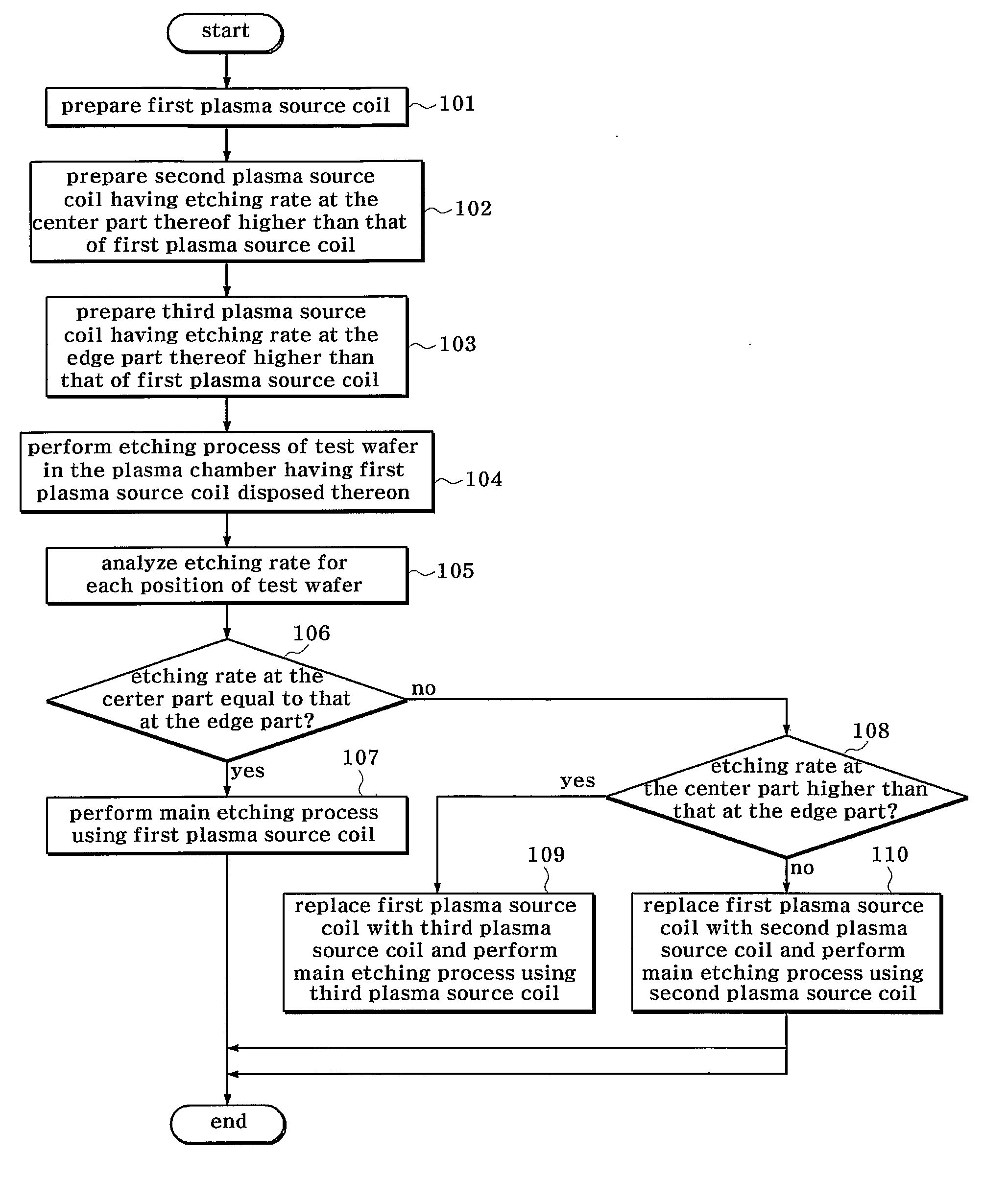
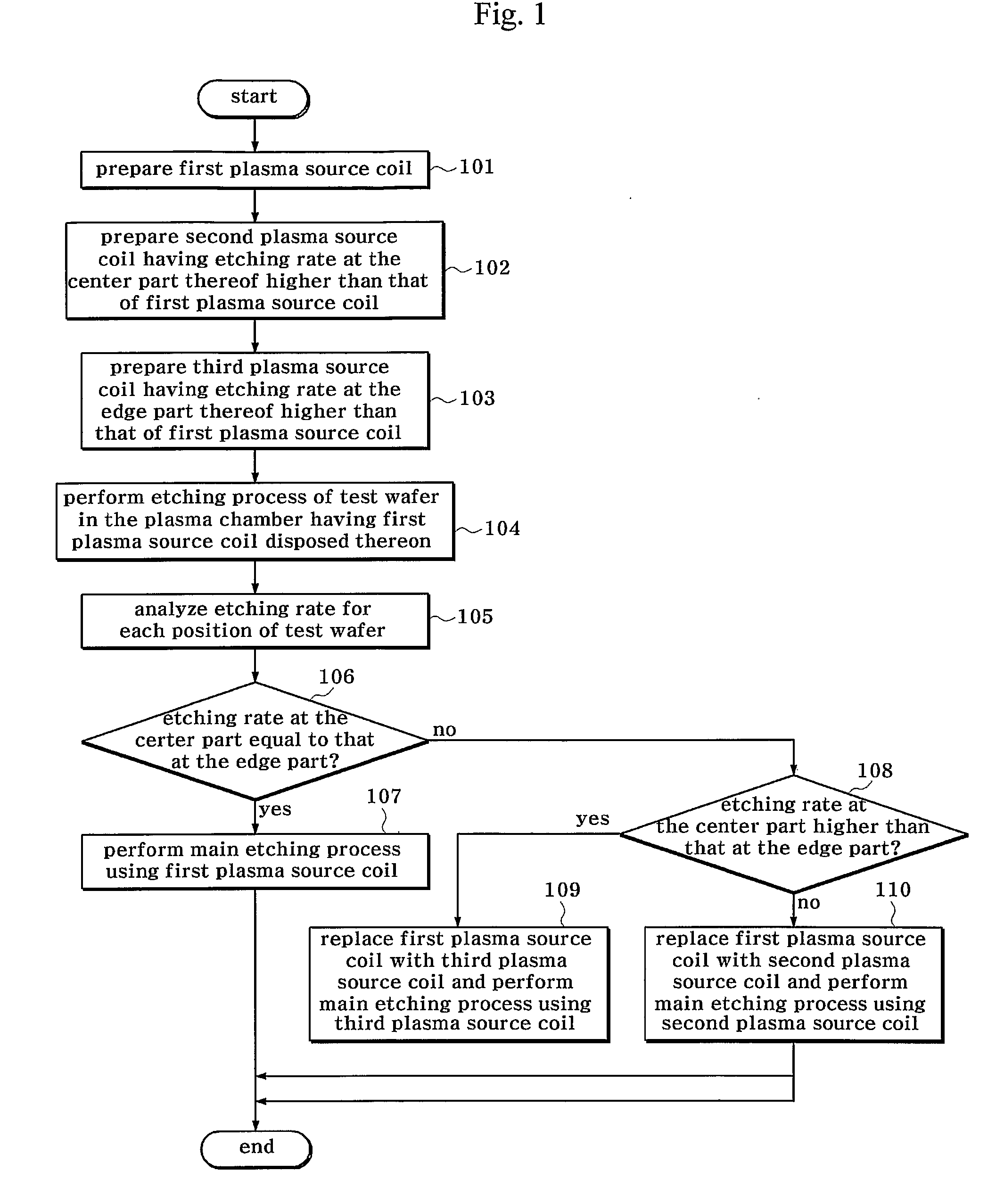
[0062]FIG. 1 is a flow chart schematically illustrating a plasma chamber setting method according to a preferred embodiment of the present invention.

[0063] As shown in FIG. 1, a first plasma source coil is prepared first (Step101). Subsequently, a second plasma source coil, which has an etching rate at the center part thereof higher than that of the first plasma source coil, is prepared (Step 102). Also, a third plasma source coil, which has an etching rate at the edge part thereof higher than that of the first plasma source coil, is prepared (Step 103). The first, second and third plasma source coils have the same plan shape while the first, second and third plasma source coils have different sectional shapes.

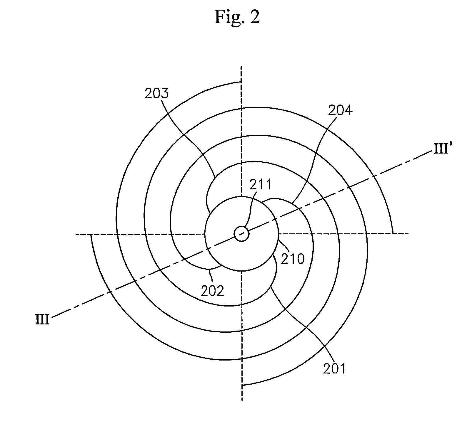
[0064] Referring to FIG. 2, each of the first, second and third plasma source coils comprises: a coil bushing 210 disposed in the center thereof; and a plurality of unit coils 201, 202, 203 and 204 helically wound on the coil bushing 210. In this embodiment, the number of th...


PUM

PropertyMeasurementUnit
source poweraaaaaaaaaa
temperatureaaaaaaaaaa
poweraaaaaaaaaa

Abstract

Disclosed herein is a plasma chamber setting method for generating plasma in a plasma chamber. A plurality of plasma source coils, including a first plasma source coil, a second plasma source coil having an etching rate at the center part thereof higher than that of the first plasma source coil, and a third plasma source coil having an etching rate at the edge part thereof higher than that of the first plasma source coil, are prepared. The first plasma source coil is disposed on the plasma chamber, and a test wafer is etched. The etching rate for each position of the test wafer is analyzed, and first plasma source coil is replaced with the second plasma source coil or the third plasma source coil based on the analysis results.

Description

TECHNICAL FIELD [0001] The present invention relates to semiconductor manufacturing equipment, and, more particularly, to a method of setting a plasma chamber having an adaptive plasma source, a plasma etching method using the same, and a method of manufacturing an adaptive plasma source. BACKGROUND ART [0002] Technology for manufacturing ultra-large scale integrated (ULSI) circuit devices has been remarkably developed for the past two decades. This remarkable development was possible with the provisions of semiconductor manufacturing equipments that are capable of supporting semiconductor-manufacturing processes requiring ultimate technology. A plasma chamber, which is one type of semiconductor manufacturing equipment, has been increasingly used in a deposition process in addition to an etching process, which is a main process of the plasma chamber. [0003] The plasma chamber is used to form plasma therein and perform processes, such as etching and deposition, with the plasma. Plasm...

Claims


Application Information

Patent Timeline
Patent Type & Authority Applications(United States)
IPC IPC(8): C23F1/00H01L21/302C03C15/00H01L21/3065H01L21/3213
CPCC23F4/00H01J37/321H01J37/32935H05H1/46H01L21/32136H01L21/32137H01J2237/334
Inventor SONG, YEONG SUOH, SANG RYONGKIM, SHEUNG KIKIM, NAM HEONOH, YOUNG KUNLEE, DO HYUNG
Owner ADAPTIVE PLASMA TECH
Learn More